
User manual

14-Pin SOIC/DIP/TSSOP Evaluation Board User’s Guide
DS51597A-page 12 © 2006 Microchip Technology Inc.
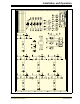
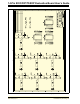
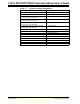
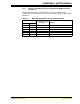
TABLE 2-1: OPTIONAL PASSIVE COMPONENTS
Device Comment
C2 Power supply bypass capacitor
C3, C4 Device filtering capacitor
C1A, C1B, C1C, C1D, C1E, C1F, C1G, C1H,
C1J, C1K, C1L, C1M, C1N, C1P
Output filter capacitor
R1A, R1B, R1C, R1D, R1E, R1F, R1G, R1H,
R1J, R1K, R1L, R1M, R1N, R1P
In-line resistance of device output
R2A, R2B, R2C, R2D, R2E, R2F, R2G, R2H,
R2J, R2K, R2L, R2M, R2N, R2P
Pull-up resistor
R3A, R3B, R3C, R3D, R3E, R3F, R3G, R3H,
R3J, R3K, R3L, R3M, R3N, R3P
Pull-down resistor
P1, P2, P3, P4, P5, P6, P7, P8 Optional passive components
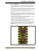
U1 14-pin DIP footprint
U2 14-pin SOIC footprint
U3 6-pin SOT-23 footprint
U4 14-pin TSSOP footprint
H1 BFMP Header Interface
J1, J2 3-pin Header for jumper connections
J3, J4, J5, J6 2-pin Header for jumper connections
S1, S2 Switch footprint