
User manual

14-Pin SOIC/DIP/TSSOP Evaluation Board User’s Guide
DS51597A-page 8 © 2006 Microchip Technology Inc.
2.3 GETTING STARTED
The 14-Pin SOIC/DIP/TSSOP Evaluation Board is a blank PCB that allows the user to
configure the circuit to the exact requirements. The passive components use the
surface-mount 805 package layout.
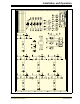
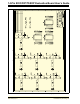
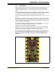
Figure 2-1 shows the evaluation board circuit. Pin “n” of each device (U1, U2 and U4)
is tied together. These pins are then connected with pad “n” of the PCB (through a
circuit). This circuit allows each pin to individually have any of the following: a pull-up
resistor, a pull-down resistor, an in-line resistor and/or a loading/filtering capacitor.
Device-filtering capacitors are available (C2 and C3), as well as a power supply filtering
capacitor (C1).
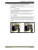
There may be cases where some additonal passive components are desired for the
evaluation circuit. The PCB has four 805 footprints that are not connected (labled P1,
P2, P3 and P4) and can easily be jumpered into the desired circuit.