
User's Manual
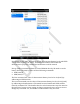


First we need to configure a RN4020 module to be in central role. For simplicity, we
call it Module A. Following commands are issued to configure such device:
Assert GPIO 3 to be low to enter command mode
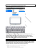
Open a terminal emulator that connects to the serial port of Module A with
following parameters:
o baud rate: 115200
o data bits: 8
o parity: none
o stop bits: 1
o flow control: hardware
+ // turn echo on
SF,1 // factory reset
SS,C0000000 // Support Device Info and Battery as server
SR,D200 // Set device as central, buffered read and support MLDP and
// UART flow control
R,1 // reboot to make changes effective
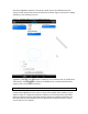
Then, we need to configure another RN4020 module to be in peripheral role. For
simplicity, we called it Module B. Following commands are issued to configure such
device:
Assert GPIO 3 to be low to enter command mode
Open a terminal emulator that connects to the serial port of Module A with
following parameters:
o baud rate: 115200
o data bits: 8
o parity: none
o stop bits: 1
o flow control: hardware
+ // turn echo on
SF,1 // factory reset
SS,30000000 // Support Heart Rate and Health Thermometer services as
// server. Notice that server services in module B overlaps
// client services in module A
SR,7200 // Set device as peripheral, buffered read, automatic
// advertisement, support MLDP and flow control features
R,1 // reboot to make changes effective
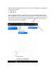
When module B is powered up, it automatically starts advertisement since auto
advertisement feature is enabled with command “SR”. Module A then could try to
connect to module B by following way:
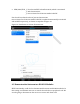
F // Start scan
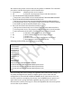
The scan result should be shown up quickly as following, where the three
elements are MAC address, MAC address type and device name respectively.