
User's Manual
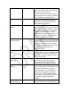

interface will not be responsive in deep sleep mode. When the module is in deep
sleep mode, GPIO 9 will output low.
GPIO 4 is used to control RN4020 when Microchip private MLDP profile is used.
Once get into MLDP mode by setting GPIO 4 at high, all data from UART will be sent
to the peer device as data stream. To exit MLDP mode, user needs to put GPIO 4 low,
so that module is back to command mode by outputting “CMD” to UART.
Setting pin BT_WAKE high is used to wake RN4020 module from dormant mode.
When RN4020 module is connected to a peer device, GPIO 5 will output high;
otherwise, GPIO 5 outputs low.
When in MLDP mode, if RN4020 needs outputting status and/or requesting
response from the host MCU, GPIO 6 will be put to high. Once RN4020 exit MLDP
mode and getting back to CMD mode, status and/or requests will be output to UART.
Once stored data is output to UART, GPIO 6 will be put to low. The maximum buffer
of status/requests is 256 bytes.
When RN4020 module is in active mode, GPIO 7 will output high; otherwise, GPIO 7
outputs low.
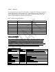
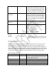
3.2 RN4020 UART Control Interface
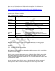
UART is the main control interface for RN4020. The default UART port configuration
for RN4020 is shown in table 2.
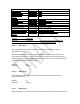
Table 2: RN4020 UART Configuration
Parameter
Value
Baud Rate
115200
Data Bits
8
Parity
None
Stop Bits
1
Flow Control
None (CTX/RTX in the
future)
The UART baud rate could be adjusted from 2400 to 932K with command “SB”.
Notice that when UART baud rate is set to 2400, there is no need to wake up the
module from GPIO 3 before communicating with the module.
All control are through AT-Commands and their parameters. All commands and
parameters are separated by comma. No space allowed between command and
parameters. All commands are finished by line feed or return.