
Information
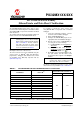


2011-2013 Microchip Technology Inc. DS80000531E-page 3
PIC32MX1XX/2XX
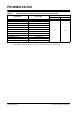
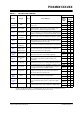
TABLE 3: SILICON ISSUE SUMMARY
Module Feature Item # Issue Summary
Affected Device
Flash
Memory
(KB)
Silicon
Revision
A0 A1
Voltage
Regulator
BOR 1.
Device may not exit Brown-out Reset (BOR) state if a BOR
event occurs.
16/32 X
64/128 X
Oscillator Clock Switch 2.
If a Fail-Safe Clock Monitor (FSCM) event occurs when
Primary Oscillator (P
OSC) mode is used, firmware clock
switch requests to switch from FRC mode will fail.
16/32 X X
64/128 X X
I
2
C™ Slave Mode 3.
The I
2
C module does not respond to address 0x78 when the
STRICT and A10M bits are cleared in the I2CxCON register.
16/32 X X
64/128 X X
USB
UIDLE
Interrupt
4. UIDLE interrupts cease if the UIDLE interrupt flag is cleared.
16/32 X X
64/128 X X
ADC — 5
The DNL parameter of the ADC module is not within the
published data sheet specifications when the ADC module is
operating at maximum conversion rate.
16/32 X X
64/128 X X
ADC
CTMU
Calibration
6. Open selection for Channel 0 positive input is not functional.
16/32 X X
64/128
ADC
Conversion
Trigger from
INT0 Interrupt
7.
The ADC module conversion triggers occur on the rising
edge of the INT0 signal even when INT0 is configured to
generate an interrupt on the falling edge.
16/32 X X
64/128 X X
Parallel
Master Port
(PMP)
Address Pins 8.
When the Parallel Master Port (PMP) module is enabled,
address pins cannot be used as GPIO output pins.
16/32 X X
64/128 X X
I/O Ports
RA0 and RA1
Pins
9.
Output High Voltage (V
OH) and internal capacitance on pins
RA0 and RA1 is not within the published data sheet
specification.
16/32 X X
64/128 X X
CPU
Data Write to a
Peripheral
10.
A data write operation by the CPU to a peripheral may be
repeated if an interrupt occurs during initial write operation.
16/32 X X
64/128 X X
Oscillator Clock Out 11.
A clock signal is present on the CLKO pin, regardless of the
clock source and setting of the CLKO Enable Configuration
bit, during a Power-on Reset (POR) condition.
16/32 X X
64/128 X X
Input
Capture
Idle Mode and
Sleep Mode 12.
All input capture modes selectable by ICM<2:0>, with the
exception of Interrupt-only mode, will not work when the
CPU enters Idle mode or Sleep mode.
16/32 X X
64/128 X X
Watchdog
Timer
(WDT)
Windowed
Mode
13. The Watchdog Timer may issue a reset even if the user tries
to clear the module within the allowed window.
16/32 X X
64/128 X X
Non-5V
Tolerant
Pins
Pull-ups 14. Internal pull-up resistors may not guarantee a logical ‘1’ on
non-5V tolerant pins when they are configured as digital
inputs.
16/32 X X
64/128 X X
5V Tolerant
Pins
Pull-ups 15. Internal pull-up resistors may not guarantee a logical ‘1’ on
5V tolerant pins when they are configured as digital inputs.
16/32 X X
64/128 X X
Legend: An ‘X’ indicates the issue is present in this revision of silicon;
Shaded cells with an Em dash (‘—’) indicate that this silicon revision does not exist for this issue;
Blank cells indicate an issue has been corrected in this revision of silicon.