
Information


PIC18F2455/2550/4455/4550
DS80220J-page 8 © 2008 Microchip Technology Inc.
17. Module: MSSP
It has been observed that following a Power-on
Reset, I
2
C mode may not initialize properly by just
configuring the SCL and SDA pins as either inputs
or outputs. This has only been seen in a few
unique system environments.
A test of a statistically significant sample of pre-
production systems, across the voltage and
current range of the application's power supply,
should indicate if a system is susceptible to this
issue.
Work around
Before configuring the module for I
2
C operation:
1. Configure the SCL and SDA pins as outputs by
clearing their corresponding TRIS bits.
2. Force SCL and SDA low by clearing the
corresponding LAT bits.
3. While keeping the LAT bits clear, configure
SCL and SDA as inputs by setting their TRIS
bits.
Once this is done, use the SSPCON1 and
SSPCON2 registers to configure the proper I
2
C
mode as before.
Date Codes that pertain to this issue:
All engineering and production devices.
18. Module: MSSP
When the MSSP is configured for SPI mode, the
Buffer Full bit, BF (SSPSTAT<0>), should not be
polled in software to determine when the transfer
is complete.
Work around
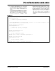
Copy the SSPSTAT register into a variable and
perform the bit test on the variable. In Example 5,
SSPSTAT is copied into the working register
where the bit test is performed.
EXAMPLE 5:
A second option is to poll the Master Synchronous
Serial Port Interrupt Flag bit, SSPIF (PIR1<3>).
This bit can be polled and will set when the transfer
is complete.
Date Codes that pertain to this issue:
All engineering and production devices.
19. Module: EUSART
In rare situations, one or more extra zero bytes
have been observed in a packet transmitted by the
module operating in Asynchronous mode. The
actual data is not lost or corrupted; only unwanted
(extra) zero bytes are observed in the packet.
This situation has only been observed when the
contents of the transmit buffer, TXREG, are trans-
ferred to the TSR during the transmission of a Stop
bit. For this to occur, three things must happen in
the same instruction cycle:
• TXREG is written to;
• the baud rate counter overflows (at the end of
the bit period); and
• a Stop bit is being transmitted (shifted out of
TSR).
Work around
If possible, do not use the module’s double-buffer
capability. Instead, load the TXREG register when
the TRMT bit (TXSTA<1>) is set, indicating the
TSR is empty.
If double-buffering is used and back-to-back
transmission is performed, then load TXREG
immediately after TXIF is set, or wait 1-bit time
after TXIF is set. Both solutions prevent writing
TXREG while a Stop bit is transmitted. Note that
TXIF is set at the beginning of the Stop bit
transmission.
If transmission is intermittent, then do the
following:
• Wait for the TRMT bit to be set before
loading TXREG.
• Alternatively, use a free timer resource to
time the baud period. Set up the timer to
overflow at the end of Stop bit, then start the
timer when you load the TXREG. Do not
load the TXREG when timer is about to
overflow.
Date Codes that pertain to this issue:
All engineering and production devices.
loop_MSB:
MOVF SSPSTAT, W
BTFSS WREG, BF
BRA loop_MSB