
Datasheet

2010 Microchip Technology Inc. DS41303G-page 347
PIC18F2XK20/4XK20
RETURN Return from Subroutine
Syntax: RETURN {s}
Operands: s [0,1]
Operation: (TOS) PC,
if s = 1
(WS) W,
(STATUSS) Status,
(BSRS) BSR,
PCLATU, PCLATH are unchanged
Status Affected: None
Encoding: 0000 0000 0001 001s
Description: Return from subroutine. The stack is
popped and the top of the stack (TOS)
is loaded into the program counter. If
‘s’= 1, the contents of the shadow
registers, WS, STATUSS and BSRS,
are loaded into their corresponding
registers, W, Status and BSR. If
‘s’ = 0, no update of these registers
occurs (default).
Words: 1
Cycles: 2
Q Cycle Activity:
Q1 Q2 Q3 Q4
Decode No
operation
Process
Data
POP PC
from stack
No
operation
No
operation
No
operation
No
operation
Example
: RETURN
After Instruction:
PC = TOS
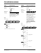
RLCF Rotate Left f through Carry
Syntax: RLCF f {,d {,a}}
Operands: 0 f 255
d [0,1]
a [0,1]
Operation: (f<n>) dest<n + 1>,
(f<7>) C,
(C) dest<0>
Status Affected: C, N, Z
Encoding: 0011 01da ffff ffff
Description: The contents of register ‘f’ are rotated
one bit to the left through the CARRY
flag. If ‘d’ is ‘0’, the result is placed in
W. If ‘d’ is ‘1’, the result is stored back
in register ‘f’ (default).
If ‘a’ is ‘0’, the Access Bank is
selected. If ‘a’ is ‘1’, the BSR is used to
select the GPR bank.
If ‘a’ is ‘0’ and the extended instruction
set is enabled, this instruction
operates in Indexed Literal Offset
Addressing mode whenever
f 95 (5Fh). See Section 24.2.3
“Byte-Oriented and Bit-Oriented
Instructions in Indexed Literal Offset
Mode” for details.
Words: 1
Cycles: 1
Q Cycle Activity:
Q1 Q2 Q3 Q4
Decode Read
register ‘f’
Process
Data
Write to
destination
Example
: RLCF REG, 0, 0
Before Instruction
REG = 1110 0110
C=0
After Instruction
REG = 1110 0110
W = 1100 1100
C=1
C
register f