
Datasheet


2010 Microchip Technology Inc. DS41303G-page 297
PIC18F2XK20/4XK20
22.5 Applications
In many applications, the ability to detect a drop below,
or rise above, a particular threshold is desirable. For
example, the HLVD module could be periodically
enabled to detect Universal Serial Bus (USB) attach or
detach. This assumes the device is powered by a lower
voltage source than the USB when detached. An attach
would indicate a high-voltage detect from, for example,
3.3V to 5V (the voltage on USB) and vice versa for a
detach. This feature could save a design a few extra
components and an attach signal (input pin).
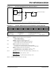
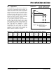
For general battery applications, Figure 22-4 shows a
possible voltage curve. Over time, the device voltage
decreases. When the device voltage reaches voltage
V
A, the HLVD logic generates an interrupt at time TA.
The interrupt could cause the execution of an ISR,
which would allow the application to perform
“housekeeping tasks” and perform a controlled
shutdown before the device voltage exits the valid
operating range at T
B. The HLVD, thus, would give the
application a time window, represented by the
difference between TA and TB, to safely exit.
FIGURE 22-4: TYPICAL LOW-VOLTAGE
DETECT APPLICATION
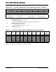
TABLE 22-1: REGISTERS ASSOCIATED WITH HIGH/LOW-VOLTAGE DETECT MODULE
Time
Voltage
VA
VB
TA
TB
VA = HLVD trip point
VB = Minimum valid device
operating voltage
Legend:
Name Bit 7 Bit 6 Bit 5 Bit 4 Bit 3 Bit 2 Bit 1 Bit 0
Reset
Values
on Page
HLVDCON VDIRMAG — IRVST HLVDEN HLVDL3 HLVDL2 HLVDL1 HLVDL0 60
INTCON GIE/GIEH PEIE/GIEL TMR0IE INT0IE RBIE TMR0IF INT0IF RBIF 59
PIR2
OSCFIF C1IF C2IF EEIF BCLIF HLVDIF TMR3IF CCP2IF 62
PIE2 OSCFIE C1IE C2IE EEIE BCLIE HLVDIE TMR3IE CCP2IE 62
IPR2 OSCFIP C1IP C2IP EEIP BCLIP HLVDIP TMR3IP CCP2IP 62
Legend: — = unimplemented, read as ‘0’. Shaded cells are unused by the HLVD module.