
Datasheet


PIC18F2XK20/4XK20
DS41303G-page 172 2010 Microchip Technology Inc.
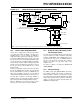
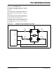
15.5 Resetting Timer3 Using the CCP
Special Event Trigger
If either of the CCP modules is configured to use
Timer3 and to generate a Special Event Trigger
in Compare mode (CCP1M<3:0> or CCP2M<3:0> =
1011), this signal will reset Timer3. It will also start an
A/D conversion if the A/D module is enabled (see
Section 11.3.4 “Special Event Trigger” for more
information).
The module must be configured as either a timer or
synchronous counter to take advantage of this feature.
When used this way, the CCPR2H:CCPR2L register
pair effectively becomes a period register for Timer3.
If Timer3 is running in Asynchronous Counter mode,
the Reset operation may not work.
In the event that a write to Timer3 coincides with a
Special Event Trigger from a CCP module, the write will
take precedence.
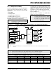
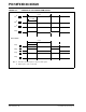
TABLE 15-1: REGISTERS ASSOCIATED WITH TIMER3 AS A TIMER/COUNTER
Note: The Special Event Triggers from the CCP2
module will not set the TMR3IF interrupt
flag bit of the PIR2 register.
Name Bit 7 Bit 6 Bit 5 Bit 4 Bit 3 Bit 2 Bit 1 Bit 0
Reset
Values
on page
INTCON GIE/GIEH PEIE/GIEL TMR0IE INT0IE RBIE TMR0IF INT0IF RBIF 59
PIR2 OSCFIF C1IF C2IF EEIF BCLIF HLVDIF TMR3IF CCP2IF 62
PIE2 OSCFIE C1IE C2IE EEIE BCLIE HLVDIE TMR3IE CCP2IE 62
IPR2
OSCFIP C1IP C2IP EEIP BCLIP HLVDIP TMR3IP CCP2IP 62
TMR3L Timer3 Register, Low Byte 61
TMR3H Timer3 Register, High Byte 61
T1CON
RD16 T1RUN T1CKPS1 T1CKPS0 T1OSCEN T1SYNC TMR1CS TMR1ON 60
T3CON RD16 T3CCP2 T3CKPS1 T3CKPS0 T3CCP1 T3SYNC
TMR3CS TMR3ON 61
Legend: — = unimplemented, read as ‘0’. Shaded cells are not used by the Timer3 module.