
Datasheet


2010-2012 Microchip Technology Inc. DS41412F-page 453
PIC18(L)F2X/4XK22
Note 1: Minimum pulse width that will consistently trigger a reset or interrupt. Shorter pulses may intermittently trigger a response.
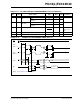
FIGURE 27-11: TIMER0 AND TIMER1 EXTERNAL CLOCK TIMINGS
TABLE 27-11: RESET, WATCHDOG TIMER, OSCILLATOR START-UP TIMER, POWER-UP TIMER
AND BROWN-OUT RESET REQUIREMENTS
Param.
No.
Symbol Characteristic Min Typ Max Units Conditions
30 TmcL MCLR
Pulse Width (low) 2 — — s
31 T
WDT
Watchdog Timer Time-out Period
(no postscaler)
3.5 4.1 4.7 ms 1:1 prescaler
32 TOST
Oscillation Start-up Timer Period 1024 TOSC — 1024 TOSC —TOSC = OSC1 period
33 T
PWRT
Power-up Timer Period 54.8 64.4 74.1 ms
34 TIOZ I/O High-Impedance from MCLR
Low or Watchdog Timer Reset
—2—s
35 TBOR
Brown-out Reset Pulse Width 200
1
—— sVDD BVDD (see
D005)
36 T
IVRST
Internal Reference Voltage Stable — 25 35 s
37 T
HLVD
High/Low-Voltage Detect Pulse
Width
200
1
—— sVDD VHLVD
38 TCSD
CPU Start-up Time 5 — 10 s
39 T
IOBST
Time for HF-INTOSC to Stabilize — 0.25 1 ms
Note: Refer to Figure 27-6 for load conditions.
46
47
45
48
41
42
40
T0CKI
T1OSO/T13CKI
TMR0 or
TMR1