
Datasheet

2010 Microchip Technology Inc. DS41303G-page 51
PIC18F2XK20/4XK20
4.0 RESET
The PIC18F2XK20/4XK20 devices differentiate
between various kinds of Reset:
a) Power-on Reset (POR)
b) MCLR
Reset during normal operation
c) MCLR Reset during power-managed modes
d) Watchdog Timer (WDT) Reset (during
execution)
e) Programmable Brown-out Reset (BOR)
f) RESET Instruction
g) Stack Full Reset
h) Stack Underflow Reset
This section discusses Resets generated by MCLR
,
POR and BOR and covers the operation of the various
start-up timers. Stack Reset events are covered in
Section 5.1.2.4 “Stack Full and Underflow Resets”.
WDT Resets are covered in Section 23.2 “Watchdog
Timer (WDT)”.
A simplified block diagram of the On-Chip Reset Circuit
is shown in Figure 4-1.
4.1 RCON Register
Device Reset events are tracked through the RCON
register (Register 4-1). The lower five bits of the regis-
ter indicate that a specific Reset event has occurred. In
most cases, these bits can only be cleared by the event
and must be set by the application after the event. The
state of these flag bits, taken together, can be read to
indicate the type of Reset that just occurred. This is
described in more detail in Section 4.6 “Reset State
of Registers”.
The RCON register also has control bits for setting
interrupt priority (IPEN) and software control of the
BOR (SBOREN). Interrupt priority is discussed in
Section 9.0 “Interrupts”. BOR is covered in
Section 4.4 “Brown-out Reset (BOR)”.
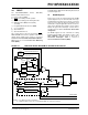
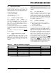
FIGURE 4-1: SIMPLIFIED BLOCK DIAGRAM OF ON-CHIP RESET CIRCUIT
External Reset
MCLR
VDD
OSC1
WDT
Time-out
V
DD
Detect
OST/PWRT
LFINTOSC
POR
OST
(2)
10-bit Ripple Counter
PWRT
(2)
11-bit Ripple Counter
Enable OST
(1)
Enable PWRT
Note 1: See Table 4-2 for time-out situations.
2: PWRT and OST counters are reset by POR and BOR. See Sections 4.3 and 4.4.
Brown-out
Reset
BOREN
RESET
Instruction
Stack
Pointer
Stack Full/Underflow Reset
Sleep
( )_IDLE
1024 Cycles
65.5 ms
32 s
MCLRE
S
R
Q
Chip_Reset