
Datasheet

PIC18F2XK20/4XK20
DS41303G-page 334 2010 Microchip Technology Inc.
DAW Decimal Adjust W Register
Syntax: DAW
Operands: None
Operation: If [W<3:0> > 9] or [DC = 1] then
(W<3:0>) + 6 W<3:0>;
else
(W<3:0>) W<3:0>;
If [W<7:4> + DC > 9] or [C = 1] then
(W<7:4>) + 6 + DC W<7:4>;
else
(W<7:4>) + DC W<7:4>
Status Affected: C
Encoding: 0000 0000 0000 0111
Description: DAW adjusts the eight-bit value in W,
resulting from the earlier addition of two
variables (each in packed BCD format)
and produces a correct packed BCD
result.
Words: 1
Cycles: 1
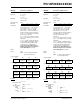
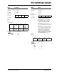
Q Cycle Activity:
Q1 Q2 Q3 Q4
Decode Read
register W
Process
Data
Write
W
Example1
:
DAW
Before Instruction
W=A5h
C=0
DC = 0
After Instruction
W = 05h
C=1
DC = 0
Example 2
:
Before Instruction
W=CEh
C=0
DC = 0
After Instruction
W = 34h
C=1
DC = 0
DECF Decrement f
Syntax: DECF f {,d {,a}}
Operands: 0 f 255
d [0,1]
a [0,1]
Operation: (f) – 1 dest
Status Affected: C, DC, N, OV, Z
Encoding: 0000 01da ffff ffff
Description: Decrement register ‘f’. If ‘d’ is ‘0’, the
result is stored in W. If ‘d’ is ‘1’, the
result is stored back in register ‘f’
(default).
If ‘a’ is ‘0’, the Access Bank is selected.
If ‘a’ is ‘1’, the BSR is used to select the
GPR bank.
If ‘a’ is ‘0’ and the extended instruction
set is enabled, this instruction operates
in Indexed Literal Offset Addressing
mode whenever f 95 (5Fh). See
Section 24.2.3 “Byte-Oriented and
Bit-Oriented Instructions in Indexed
Literal Offset Mode” for details.
Words: 1
Cycles: 1
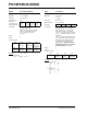
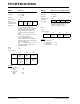
Q Cycle Activity:
Q1 Q2 Q3 Q4
Decode Read
register ‘f’
Process
Data
Write to
destination
Example
: DECF CNT, 1, 0
Before Instruction
CNT = 01h
Z=0
After Instruction
CNT = 00h
Z=1