
Datasheet


PIC18F45J10 FAMILY
DS39682E-page 162 © 2009 Microchip Technology Inc.
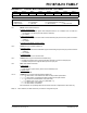
REGISTER 16-5: SSPxCON2: MSSPx CONTROL REGISTER 2 (I
2
C™ MASTER MODE)
R/W-0 R/W-0 R/W-0 R/W-0 R/W-0 R/W-0 R/W-0 R/W-0
GCEN ACKSTAT ACKDT
(1)
ACKEN
(2)
RCEN
(2)
PEN
(2)
RSEN
(2)
SEN
(2)
bit 7 bit 0
Legend:
R = Readable bit W = Writable bit U = Unimplemented bit, read as ‘0’
-n = Value at POR ‘1’ = Bit is set ‘0’ = Bit is cleared x = Bit is unknown
bit 7 GCEN: General Call Enable bit
Unused in Master mode.
bit 6 ACKSTAT: Acknowledge Status bit (Master Transmit mode only)
1 = Acknowledge was not received from slave
0 = Acknowledge was received from slave
bit 5 ACKDT: Acknowledge Data bit (Master Receive mode only)
(1)
1 = Not Acknowledge
0 = Acknowledge
bit 4 ACKEN: Acknowledge Sequence Enable bit
(2)
1 = Initiate Acknowledge sequence on SDAx and SCLx pins and transmit ACKDT data bit.
Automatically cleared by hardware.
0 = Acknowledge sequence Idle
bit 3 RCEN: Receive Enable bit (Master Receive mode only)
(2)
1 = Enables Receive mode for I
2
C
0 = Receive Idle
bit 2 PEN: Stop Condition Enable bit
(2)
1 = Initiate Stop condition on SDAx and SCLx pins. Automatically cleared by hardware.
0 = Stop condition Idle
bit 1 RSEN: Repeated Start Condition Enable bit
(2)
1 = Initiate Repeated Start condition on SDAx and SCLx pins. Automatically cleared by hardware.
0 = Repeated Start condition Idle
bit 0 SEN: Start Condition Enable bit
(2)
1 = Initiate Start condition on SDAx and SCLx pins. Automatically cleared by hardware.
0 = Start condition Idle
Note 1: Value that will be transmitted when the user initiates an Acknowledge sequence at the end of a receive.
2: If the I
2
C module is active, these bits may not be set (no spooling) and the SSPxBUF may not be written
(or writes to the SSPxBUF are disabled).