
Datasheet


© 2009 Microchip Technology Inc. DS39632E-page 165
PIC18F2455/2550/4455/4550
17.0 UNIVERSAL SERIAL BUS
(USB)
This section describes the details of the USB
peripheral. Because of the very specific nature of the
module, knowledge of USB is expected. Some
high-level USB information is provided in
Section 17.10 “Overview of USB” only for application
design reference. Designers are encouraged to refer to
the official specification published by the USB Imple-
menters Forum (USB-IF) for the latest information.
USB specification Revision 2.0 is the most current
specification at the time of publication of this document.
17.1 Overview of the USB Peripheral
The PIC18FX455/X550 device family contains a
full-speed and low-speed compatible USB Serial Inter-
face Engine (SIE) that allows fast communication
between any USB host and the PIC
®
microcontroller.
The SIE can be interfaced directly to the USB, utilizing
the internal transceiver, or it can be connected through
an external transceiver. An internal 3.3V regulator is
also available to power the internal transceiver in 5V
applications.
Some special hardware features have been included to
improve performance. Dual port memory in the
device’s data memory space (USB RAM) has been
supplied to share direct memory access between the
microcontroller core and the SIE. Buffer descriptors are
also provided, allowing users to freely program end-
point memory usage within the USB RAM space. A
Streaming Parallel Port has been provided to support
the uninterrupted transfer of large volumes of data,
such as isochronous data, to external memory buffers.
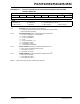
Figure 17-1 presents a general overview of the USB
peripheral and its features.
FIGURE 17-1: USB PERIPHERAL AND OPTIONS
UOE
(1)
1Kbyte
USB RAM
USB
SIE
USB Control and
VM
(1)
VP
(1)
RCV
(1)
VMO
(1)
VPO
(1)
Transceiver
External
Transceiver
P
P
EN
3.3V Regulator
D+
D-
Internal Pull-ups
UOE
VUSB
External 3.3V
Supply
(3)
FSEN
UPUEN
UTRDIS
USB Clock from the
Oscillator Module
VREGEN
Optional
External
Pull-ups
(2)
(Low
(Full
PIC18FX455/X550 Family
SPP7:SPP0
USB Bus
USB Bus
FS
Speed)
Speed)
Note 1: This signal is only available if the internal transceiver is disabled (UTRDIS = 1).
2: The internal pull-up resistors should be disabled (UPUEN = 0) if external pull-up resistors are used.
3: Do not enable the internal regulator when using an external 3.3V supply.
Configuration
CK1SPP
CK2SPP
CSSPP
OESPP