
Datasheet


PIC18F2455/2550/4455/4550
DS39632E-page 108 © 2009 Microchip Technology Inc.
9.5 IPR Registers
The IPR registers contain the individual priority bits for
the peripheral interrupts. Due to the number of
peripheral interrupt sources, there are two Peripheral
Interrupt Priority registers (IPR1 and IPR2). Using the
priority bits requires that the Interrupt Priority Enable
(IPEN) bit be set.
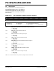
REGISTER 9-8: IPR1: PERIPHERAL INTERRUPT PRIORITY REGISTER 1
R/W-1 R/W-1 R/W-1 R/W-1 R/W-1 R/W-1 R/W-1 R/W-1
SPPIP
(1)
ADIP RCIP TXIP SSPIP CCP1IP TMR2IP TMR1IP
bit 7 bit 0
Legend:
R = Readable bit W = Writable bit U = Unimplemented bit, read as ‘0’
-n = Value at POR ‘1’ = Bit is set ‘0’ = Bit is cleared x = Bit is unknown
bit 7 SPPIP: Streaming Parallel Port Read/Write Interrupt Priority bit
(1)
1 = High priority
0 = Low priority
bit 6 ADIP: A/D Converter Interrupt Priority bit
1 = High priority
0 = Low priority
bit 5 RCIP: EUSART Receive Interrupt Priority bit
1 = High priority
0 = Low priority
bit 4 TXIP: EUSART Transmit Interrupt Priority bit
1 = High priority
0 = Low priority
bit 3 SSPIP: Master Synchronous Serial Port Interrupt Priority bit
1 = High priority
0 = Low priority
bit 2 CCP1IP: CCP1 Interrupt Priority bit
1 = High priority
0 = Low priority
bit 1 TMR2IP: TMR2 to PR2 Match Interrupt Priority bit
1 = High priority
0 = Low priority
bit 0 TMR1IP: TMR1 Overflow Interrupt Priority bit
1 = High priority
0 = Low priority
Note 1: This bit is reserved on 28-pin devices; always maintain this bit clear.