
Datasheet


© 2008 Microchip Technology Inc. DS39631E-page 101
PIC18F2420/2520/4420/4520
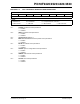
REGISTER 9-9: IPR2: PERIPHERAL INTERRUPT PRIORITY REGISTER 2
R/W-1 R/W-1 U-0 R/W-1 R/W-1 R/W-1 R/W-1 R/W-1
OSCFIP CMIP
— EEIP BCLIP HLVDIP TMR3IP CCP2IP
bit 7 bit 0
Legend:
R = Readable bit W = Writable bit U = Unimplemented bit, read as ‘0’
-n = Value at POR ‘1’ = Bit is set ‘0’ = Bit is cleared x = Bit is unknown
bit 7 OSCFIP: Oscillator Fail Interrupt Priority bit
1 =High priority
0 = Low priority
bit 6 CMIP: Comparator Interrupt Priority bit
1 =High priority
0 = Low priority
bit 5 Unimplemented: Read as ‘0’
bit 4 EEIP: Data EEPROM/Flash Write Operation Interrupt Priority bit
1 =High priority
0 = Low priority
bit 3 BCLIP: Bus Collision Interrupt Priority bit
1 =High priority
0 = Low priority
bit 2 HLVDIP: High/Low-Voltage Detect Interrupt Priority bit
1 =High priority
0 = Low priority
bit 1 TMR3IP: TMR3 Overflow Interrupt Priority bit
1 =High priority
0 = Low priority
bit 0 CCP2IP: CCP2 Interrupt Priority bit
1 =High priority
0 = Low priority