
Information
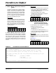
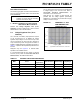
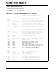
Table Of Contents
- TABLE 1: Silicon DEVREV Values
- TABLE 2: Silicon Issue Summary
- Silicon Errata Issues
- Data Sheet Clarifications
- Appendix A: Document Revision History
- Worldwide Sales and Service
PIC18F47J13 FAMILY
DS80503E-page 6 2011 Microchip Technology Inc.
2.4.1 CONSIDERATIONS FOR CERAMIC
CAPACITORS
In recent years, large value, low-voltage, surface
mount ceramic capacitors have become very cost
effective in sizes up to a few tens of microfarad. The
low-ESR, small physical size and other properties
make ceramic capacitors very attractive in many types
of applications.
Ceramic capacitors are suitable for use with the
internal voltage regulator of this microcontroller. How-
ever, some care is needed in selecting the capacitor to
ensure that it maintains sufficient capacitance over the
intended operating range of the application.
Typical low-cost, 10 µF ceramic capacitors are
available in X5R, X7R and Y5V dielectric ratings (other
types are also available, but are less common). The
initial tolerance specifications for these types of capac-
itors are often specified as ±10% to ±20% (X5R and
X7R), or -20%/+80% (Y5V). However, the effective
capacitance that these capacitors provide in an
application circuit will also vary based on additional
factors, such as the applied DC bias voltage and the
temperature. The total in-circuit tolerance is, therefore,
much wider than the initial tolerance specification.
The X5R and X7R capacitors typically exhibit satisfac-
tory temperature stability (ex: ±15% over a wide
temperature range, but consult the manufacturer’s data
sheets for exact specifications). However, Y5V capaci-
tors typically have extreme temperature tolerance
specifications of +22%/-82%. Due to the extreme tem-
perature tolerance, a 10 µF nominal rated Y5V type
capacitor may not deliver enough total capacitance to
meet minimum internal voltage regulator stability and
transient response requirements. Therefore, Y5V
capacitors are not recommended for use with the
internal voltage regulator if the application must
operate over a wide temperature range.
In addition to temperature tolerance, the effective
capacitance of large value ceramic capacitors can vary
substantially, based on the amount of DC voltage
applied to the capacitor. This effect can be very signifi-
cant, but is often overlooked or is not always
documented.
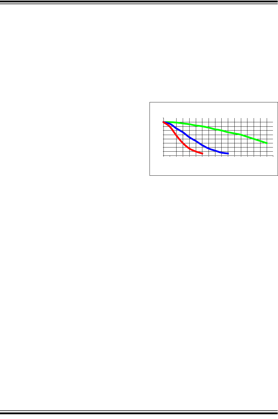
A typical DC bias voltage vs. capacitance graph for
16V, 10V and 6.3V rated capacitors is shown in
Figure 2-4.
FIGURE 2-4 DC BIAS VOLTAGE vs.
CAPACITANCE
CHARACTERISTICS
When selecting a ceramic capacitor to be used with the
internal voltage regulator, it is suggested to select a
high-voltage rating, so that the operating voltage is a
small percentage of the maximum rated capacitor volt-
age. For example, choose a ceramic capacitor rated at
16V for the 2.5V core voltage. Suggested capacitors
are shown in Table 2-1.
-80
-70
-60
-50
-40
-30
-20
-10
0
10
5 1011121314151617
DC Bias Voltage(VDC)
Capacitance Change(%)
01234 6789
16V Capacitor
10V Capacitor
6.3V Capacitor