
Information
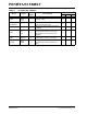
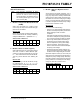
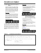
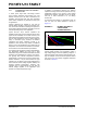
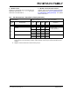
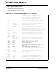
Table Of Contents
- TABLE 1: Silicon DEVREV Values
- TABLE 2: Silicon Issue Summary
- Silicon Errata Issues
- Data Sheet Clarifications
- Appendix A: Document Revision History
- Worldwide Sales and Service
2011 Microchip Technology Inc. DS80503E-page 5
PIC18F47J13 FAMILY
Data Sheet Clarifications
The following typographic corrections and clarifications
are to be noted for the latest version of the device data
sheet (DS39974A):
1. Module: Guidelines for Getting Started
with PIC18FJ Microcontrollers
Section “2.4 Voltage Regulator Pins (VCAP/
V
DDCORE)” has been replaced with a new and more
detailed section. The entire text follows:
2.4 Voltage Regulator Pins (VCAP/
V
DDCORE)
On “F” devices, a low-ESR (< 5Ω) capacitor is required
on the V
CAP/VDDCORE pin to stabilize the voltage
regulator output voltage. The V
CAP/VDDCORE pin must
not be connected to V
DD and must use a capacitor of
10 µF connected to ground. The type can be ceramic or
tantalum. Suitable examples of capacitors are shown in
Table 2-1. Capacitors with equivalent specifications can
be used.
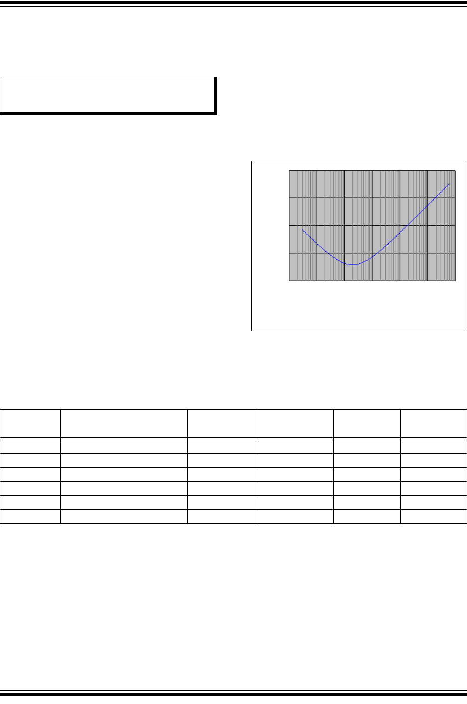
Designers may use Figure 2-3 to evaluate ESR
equivalence of candidate devices.
It is recommended that the trace length not exceed
0.25 inch (6 mm). Refer to Section 30.0 “Electrical
Characteristics” for additional information.
On “LF” devices, the V
CAP/VDDCORE pin must be tied to
a voltage supply at the V
DDCORE level. Refer to
Section 30.0 “Electrical Characteristics” for
information on VDD and VDDCORE.
Note that the “LF” versions of these devices are
provided with the voltage regulator permanently
disabled; they must always be provided with a supply
voltage on the V
DDCORE pin.
FIGURE 2-3 FREQUENCY vs. ESR
PERFORMANCE FOR
SUGGESTED V
CAP
.
Note: Corrections are shown in bold. Where
possible, the original bold text formatting
has been removed for clarity.
10
1
0.1
0.01
0.001
0.01 0.1 1 10 100 1000 10,000
Frequency (MHz)
ESR ()
Note: Typical data measurement at 25°C, 0V DC bias.
TABLE 2-1 SUITABLE CAPACITOR EQUIVALENTS
Make Part #
Nominal
Capacitance
Base Tolerance Rated Voltage Temp. Range
TDK C3216X7R1C106K 10 µF ±10% 16V -55 to 125ºC
TDK C3216X5R1C106K 10 µF ±10% 16V -55 to 85ºC
Panasonic ECJ-3YX1C106K 10 µF ±10% 16V -55 to 125ºC
Panasonic ECJ-4YB1C106K 10 µF ±10% 16V -55 to 85ºC
Murata GRM32DR71C106KA01L 10 µF ±10% 16V -55 to 125ºC
Murata GRM31CR61C106KC31L 10 µF ±10% 16V -55 to 85ºC