
Datasheet


2010 Microchip Technology Inc. Preliminary DS39974A-page 511
PIC18F47J13 FAMILY
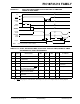
FIGURE 30-7: RESET, WATCHDOG TIMER, OSCILLATOR START-UP TIMER AND
POWER-UP TIMER TIMING
TABLE 30-14: RESET, WATCHDOG TIMER, OSCILLATOR START-UP TIMER, POWER-UP TIMER
AND BROWN-OUT RESET REQUIREMENTS
Param.
No.
Symbol Characteristic Min Typ Max Units Conditions
30 T
MCLMCLR Pulse Width (low) 2 — — s
31 TWDT Watchdog Timer Time-out Period
(no postscaler)
2.67 4.0 5.53 ms
32 T
OST Oscillator Start-up Timer Period 1024 TOSC — 1024 TOSC —TOSC = OSC1 period
33 TPWRT Power-up Timer Period —
—
500
46
—
—
s
ms
F Devices
LF Devices
34 T
IOZ I/O High-Impedance from MCLR
Low or Watchdog Timer Reset
——3 TCY + 2 s (Note 1)
36 T
IRVST Time for Internal Reference
Voltage to become Stable
—20—s
37 T
LVD High/Low-Voltage Detect
Pulse Width
—200— s
38 T
CSD CPU Start-up Time — 200 — s (Note 2)
Note 1: The maximum T
IOZ is the lesser of (3 TCY + 2 s) or 700 s.
2: MCLR
rising edge to code execution, assuming TPWRT (and TOST if applicable) has already expired.
VDD
MCLR
Internal
POR
PWRT
Time-out
Oscillator
Time-out
Internal
Reset
Watchdog
Timer
Reset
33
32
30
31
34
I/O pins
34
Note: Refer to Figure 30-4 for load conditions.