
Information


2010 Microchip Technology Inc. DS41303G-page 29
PIC18F2XK20/4XK20
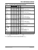
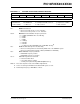
REGISTER 2-1: OSCCON: OSCILLATOR CONTROL REGISTER
R/W-0 R/W-0 R/W-1 R/W-1 R-q R-0 R/W-0 R/W-0
IDLEN IRCF2 IRCF1 IRCF0 OSTS
(1)
IOFS SCS1 SCS0
bit 7 bit 0
Legend:
R = Readable bit W = Writable bit U = Unimplemented bit, read as ‘0’ q = depends on condition
-n = Value at POR ‘1’ = Bit is set ‘0’ = Bit is cleared x = Bit is unknown
bit 7 IDLEN: Idle Enable bit
1 = Device enters Idle mode on SLEEP instruction
0 = Device enters Sleep mode on SLEEP instruction
bit 6-4 IRCF<2:0>: Internal Oscillator Frequency Select bits
111 = 16 MHz (HFINTOSC drives clock directly)
110 = 8 MHz
101 = 4 MHz
100 = 2 MHz
011 = 1 MHz
(3)
010 = 500 kHz
001 = 250 kHz
000 = 31 kHz (from either HFINTOSC/512 or LFINTOSC directly)
(2)
bit 3 OSTS: Oscillator Start-up Time-out Status bit
(1)
1 = Device is running from the clock defined by FOSC<2:0> of the CONFIG1 register
0 = Device is running from the internal oscillator (HFINTOSC or LFINTOSC)
bit 2 IOFS: HFINTOSC Frequency Stable bit
1 = HFINTOSC frequency is stable
0 = HFINTOSC frequency is not stable
bit 1-0 SCS<1:0>: System Clock Select bits
1x = Internal oscillator block
01 = Secondary (Timer1) oscillator
00 = Primary clock (determined by CONFIG1H[FOSC<3:0>]).
Note 1: Reset state depends on state of the IESO Configuration bit.
2: Source selected by the INTSRC bit of the OSCTUNE register, see text.
3: Default output frequency of HFINTOSC on Reset.