
Information

2010 Microchip Technology Inc. DS41303G-page 221
PIC18F2XK20/4XK20
17.4.7 BAUD RATE
In I
2
C Master mode, the Baud Rate Generator (BRG)
reload value is placed in the SSPADD register
(Figure 17-17). When a write occurs to SSPBUF, the
Baud Rate Generator will automatically begin counting.
The BRG counts down to ‘0’ and stops until another
reload has taken place. The BRG count is decre-
mented twice per instruction cycle (T
CY) on the Q2 and
Q4 clocks. In I
2
C Master mode, the BRG is reloaded
automatically. One half of the SCL period is equal to
[(SSPADD+1) 2]/FOSC. Therefore SSPADD =
(F
CY/FSCL) -1.
Once the given operation is complete (i.e.,
transmission of the last data bit is followed by ACK
), the
internal clock will automatically stop counting and the
SCL pin will remain in its last state.
Table 17-3 demonstrates clock rates based on
instruction cycles and the BRG value loaded into
SSPADD.
The minimum SSPADD value for baud rate generation
is 0x03.
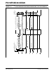
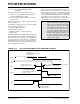
FIGURE 17-17: BAUD RATE GENERATOR BLOCK DIAGRAM
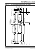
TABLE 17-3: I
2
C™ CLOCK RATE W/BRG
SSPM<3:0>
BRG Down Counter
CLKOUT
F
OSC/2
SSPADD<7:0>
SSPM<3:0>
SCL
Reload
Control
Reload
FOSC FCY BRG Value
F
SCL
(2 Rollovers of BRG)
64 MHz 16 MHz 27h 400 kHz
(1)
64 MHz 16 MHz 32h 313.7 kHz
64 MHz 16 MHz 3Fh 250 kHz
40 MHz 10 MHz 18h 400 kHz
(1)
40 MHz 10 MHz 1Fh 312.5 kHz
40 MHz 10 MHz 63h 100 kHz
16 MHz 4 MHz 09h 400 kHz
(1)
16 MHz 4 MHz 0Ch 308 kHz
16 MHz 4 MHz 27h 100 kHz
4 MHz 1 MHz 09h 100 kHz
Note 1: The I
2
C interface does not conform to the 400 kHz I
2
C specification (which applies to rates greater than
100 kHz) in all details, but may be used with care where higher rates are required by the application.