
Information


PIC18F2XK20/4XK20
DS41303G-page 180 2010 Microchip Technology Inc.
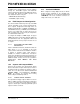
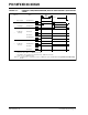
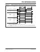
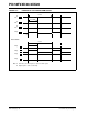
FIGURE 16-7: EXAMPLE OF FULL-BRIDGE PWM OUTPUT
Period
Pulse Width
P1A
(2)
P1B
(2)
P1C
(2)
P1D
(2)
Forward Mode
(1)
Period
Pulse Width
P1A
(2)
P1C
(2)
P1D
(2)
P1B
(2)
Reverse Mode
(1)
(1)
(1)
Note 1: At this time, the TMR2 register is equal to the PR2 register.
2: Output signal is shown as active-high.