
Information


2010 Microchip Technology Inc. DS41303G-page 13
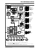
PIC18F2XK20/4XK20
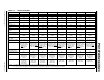
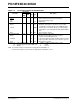
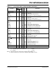
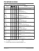
TABLE 1-1: DEVICE FEATURES
Features PIC18F23K20 PIC18F24K20 PIC18F25K20 PIC18F26K20 PIC18F43K20 PIC18F44K20 PIC18F45K20 PIC18F46K20
Operating Frequency
(2)
DC – 64 MHz DC – 64 MHz DC – 64 MHz DC – 64 MHz DC – 64 MHz DC – 64 MHz DC – 64 MHz DC – 64 MHz
Program Memory (Bytes) 8192 16384 32768 65536 8192 16384 32768 65536
Program Memory
(Instructions)
4096 8192 16384 32768 4096 8192 16384 32768
Data Memory (Bytes) 512 768 1536 3936 512 768 1536 3936
Data EEPROM Memory
(Bytes)
256 256 256 1024 256 256 256 1024
Interrupt Sources 19 19 19 19 20 20 20 20
I/O Ports A, B, C, (E)
(1)
A, B, C, (E)
(1)
A, B, C, (E)
(1)
A, B, C, (E)
(1)
A, B, C, D, E A, B, C, D, E A, B, C, D, E A, B, C, D, E
Timers 4 4 44 44 44
Capture/Compare/PWM
Modules
11111111
Enhanced Capture/
Compare/PWM Modules
1 1 11 11 11
Serial Communications MSSP, Enhanced
USART
MSSP, Enhanced
USART
MSSP, Enhanced
USART
MSSP, Enhanced
USART
MSSP, Enhanced
USART
MSSP, Enhanced
USART
MSSP, Enhanced
USART
MSSP, Enhanced
USART
Parallel Communica-
tions (PSP)
No No No No Yes Yes Yes Yes
10-bit Analog-to-Digital
Module
1 internal plus 10
Input Channels
1 internal plus 10
Input Channels
1 internal plus 10
Input Channels
1 internal plus 10
Input Channels
1 internal plus 13
Input Channels
1 internal plus 13
Input Channels
1 internal plus 13
Input Channels
1 internal plus 13
Input Channels
Resets (and Delays) POR, BOR, RESET
Instruction, Stack
Full, Stack Underflow
(PWRT, OST),
MCLR
(optional),
WDT
POR, BOR, RESET
Instruction, Stack
Full, Stack Underflow
(PWRT, OST), MCLR
(optional), WDT
POR, BOR, RESET
Instruction, Stack
Full, Stack Underflow
(PWRT, OST),
MCLR
(optional),
WDT
POR, BOR, RESET
Instruction, Stack
Full, Stack Underflow
(PWRT, OST), MCLR
(optional), WDT
POR, BOR, RESET
Instruction, Stack
Full, Stack Underflow
(PWRT, OST),
MCLR
(optional),
WDT
POR, BOR, RESET
Instruction, Stack
Full, Stack Underflow
(PWRT, OST),
MCLR
(optional),
WDT
POR, BOR, RESET
Instruction, Stack
Full, Stack Underflow
(PWRT, OST),
MCLR
(optional),
WDT
POR, BOR, RESET
Instruction, Stack
Full, Stack Underflow
(PWRT, OST), MCLR
(optional), WDT
Programmable High/
Low-Voltage Detect
Yes Yes Yes Yes Yes Yes Yes Yes
Programmable Brown-
out Reset
Yes Yes Yes Yes Yes Yes Yes Yes
Instruction Set 75 Instructions; 83
with Extended
Instruction Set
enabled
75 Instructions; 83
with Extended
Instruction Set
enabled
75 Instructions; 83
with Extended
Instruction Set
enabled
75 Instructions; 83
with Extended
Instruction Set
enabled
75 Instructions; 83
with Extended
Instruction Set
enabled
75 Instructions; 83
with Extended
Instruction Set
enabled
75 Instructions; 83
with Extended
Instruction Set
enabled
75 Instructions; 83
with Extended
Instruction Set
enabled
Packages 28-pin PDIP
28-pin SOIC
28-pin QFN
28-pin SSOP
28-pin UQFN
28-pin PDIP
28-pin SOIC
28-pin QFN
28-pin SSOP
28-pin PDIP
28-pin SOIC
28-pin QFN
28-pin SSOP
28-pin PDIP
28-pin SOIC
28-pin QFN
28-pin SSOP
40-pin PDIP
44-pin QFN
44-pin TQFP
40-pin PDIP
44-pin QFN
44-pin TQFP
40-pin PDIP
44-pin QFN
44-pin TQFP
40-pin PDIP
44-pin QFN
44-pin TQFP
Note 1: PORTE contains the single RE3 read-only bit. The LATE and TRISE registers are not implemented.
2: Frequency range shown applies to industrial range devices only. Maximum frequency for extended range devices is 48 MHz.