
Information


PIC18F47J53 FAMILY
DS80506C-page 4 2010 Microchip Technology Inc.
4. Module: EUSART (Receive Baud Rate)
The EUSART may transmit and receive at
different baud rates under the following
circumstances:
• a system clock source other than the
Secondary Oscillator has been selected, and
• a CPU clock divider (CPDIV<1:0>,
CONFIG1H<1:0>) other than 1:1 has been
programmed.
This is because the receive baud rate clock
source is generated from a point prior to the
CPU prescaler, while the rest of the logic is
clocked at the system clock frequency (following
the prescaler).
Work around
Several work arounds are presented; others
may be available.
• If possible, use only a CPU divider of 1:1
(CPDIV<1:0> = 11).
• If the EUSART is being used to receive data
only, calculate the baud rate on the predivided
clock frequency. For example, if the system
clock frequency is 8 MHz and a CPU divider
setting of 2 is being used, use a clock
frequency of 16 MHz to calculate baud rate.
• Use two USART modules for communication:
one to transmit data, and one to receive.
Calculate the baud rate for the receive
USART as described in the previous work
around. Calculate the transmit baud rate
normally using the actual (post-divider) clock
speed.
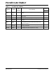
Affected Silicon Revisions
5. Module: Master Synchronous Serial Port
In Master I
2
C Receive mode, if a Stop condition
occurs in the middle of an address or data
reception, the SCL clock stream will continue
endlessly and the RCEN bit of the SSPxCON2
register will remain set improperly. When a Start
condition occurs after the improper Stop condi-
tion, nine additional clocks will be generated
followed by the RCEN bit going low.
Work around
Use low-impedance pull-ups on the SDA line to
reduce the possibility of noise glitches that may
trigger an improper Stop event. Use a time-out
event timer to detect the unexpected Stop con-
dition, and subsequently, the stuck RCEN bit.
Clear the stuck RCEN bit by clearing the SSPEN
bit of SSPxCON1.
Affected Silicon Revisions
6. Module: Master Synchronous Serial Port
(MSSP)
When configured for I
2
C™ slave reception, the
MSSP module may not receive the correct data, in
extremely rare cases. This occurs only if the Serial
Receive/Transmit Buffer register (SSPxBUF) is
not read after the SSP1IF interrupt (PIR1<3>) has
occurred, but before the first rising clock edge of
the next byte being received.
Work around
The issue can be resolved in either of these ways:
• Prior to the I
2
C slave reception, enable the
clock stretching feature. This is done by setting
the SEN bit (SSPxCON2<0>).
• Each time the SSPxIF is set, read the
SSPxBUF before the first rising clock edge of
the next byte being received.
A1
X
A1
X
A1
X