
Datasheet


PIC18F24/25/44/45K20
DS80366G-page 6 © 2009 Microchip Technology Inc.
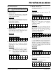
21. Module: Clocks
EC Mode operation is limited to a maximum of
48 MHz (Rev. A4 and A7 only).
Work around
Divide external clock by 4 and use HS-PLL Clock
mode for external clocking above 48 MHz.
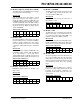
Affected Silicon Revisions
22. Module: Comparators
When the CxON bit is clear, the output from the
comparator will be properly forced to zero, but the
CxPOL bit will improperly have no effect on the
CxOUT bit. This prevents presetting the
comparator change-on-interrupt mismatch latches
as described in the data sheet.
Work around
Configure one of the unused comparator input
channels as a digital output. Use that digital output
to manipulate the comparator output to the desired
CxOUT non-interrupt level. When the comparator
is then set to the desired inputs, the mismatch
latches will be preset to the non-interrupt level and
the CxIF flag can then be cleared.
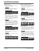
Affected Silicon Revisions
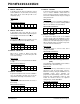
23. Module: Data EEPROM Memory
The write/erase endurance of Data EE Memory is
limited to 10K cycles.
Work around
Use error correction method that stores data in
multiple locations.
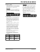
Affected Silicon Revisions
24. Module: Program Flash Memory
The write/erase endurance of the PFM is limited to
1K cycles when V
DD is above 3V. Endurance
degrades when V
DD is below 3V.
Work around
For data tables in program Flash memory use
error correction method that stores data in multiple
locations.
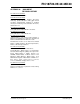
Affected Silicon Revisions
25. Module: Configuration Bits
Bit 3 of CONFIG3H defaults to ‘0’ after a Bulk
Erase instead of ‘1’ as specified in the data sheet.
Work around
Program the HFOFST bit to the desired state after
a Bulk Erase. All MPLAB
®
IDE programming tools
currently perform this way.
Affected Silicon Revisions
26. Module: EUSART
In Asynchronous Receive mode, the RCIDL bit of
the BAUDCON register will properly go low when
an invalid Start bit less than 1/8th of a bit time is
received. The RCIDL bit will then stay low
improperly until a valid Start bit is received.
Work around
When monitoring the RCIDL bit, measure the
length of time between the RCIDL going low and
the RCIF flag going high. If this time is greater than
one character time, then restore the RCIDL bit by
resetting the EUSART module. The EUSART
module is reset when the SPEN bit of the RCSTA
register is cleared.
Affected Silicon Revisions
A4 A7 A9 AB
XX
A4 A7 A9 AB
XXX
X
A4 A7 A9
AB
XXX
X
A4 A7 A9 AB
XXX
X
A4 A7 A9 AB
XXX
X
A4 A7 A9
AB
XXX
X