
Datasheet
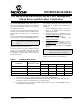

PIC18F24/25/44/45K20
DS80366G-page 4 © 2009 Microchip Technology Inc.
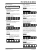
8. Module: MSSP SPI
In SPI Master mode, when the CKE bit is cleared
and the SMP bit is set, the last bit of the incoming
data stream (bit 0) at the SDI pin will not be
sampled properly.
Work around
None.
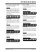
Affected Silicon Revisions
9. Module: MSSP SPI
In SPI Master mode, when CKE bit is set, the
SSPBUF will reload the SSPSR output shift register
on every high-to-low transition of the SS
pin.
Work around
Avoid using the SS pin when the CKE bit is set and
the MSSP is configured for SPI Master mode.
Affected Silicon Revisions
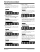
10. Module: MSSP SPI
When SPI is enabled in Master mode with
CKE = 1 and CKP = 0, a 1/F
OSC wide pulse will
occur on the SCK pin.
Work around
Configure SCK pin as an input until after the MSSP
is setup.
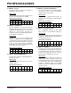
Affected Silicon Revisions
11. Module: EUSART
In Synchronous Master mode, when the SPBRG is
set to an odd number, the duty cycle of the CK
output will be skewed by one baud clock count.
Work around
High values of SPBRG will minimize the effect of
this anomaly.
Affected Silicon Revisions
12. Module: EUSART
In Synchronous Master mode, when the SPBRG is
set to 3 and the TXREG is written while the
previous character is still in the TX shift register, the
LS bit of the TXREG character may be corrupted
during transmission.
Work around
When SPBRG is set to 3, wait until the TRMT bit of
the TXSTA register is set before loading TXREG
with the next character to be transmitted.
Affected Silicon Revisions
13. Module: EUSART
In Synchronous Master mode, if the SPBRG
register is equal to 0 when the TXEN bit is set, then
writing to TXREG will properly start transmission.
However, the clock will be improperly out of phase
with the data bits and the clock will not stop at the
end of the character transmission.
Work around
Set SPBRG register to non-zero value before
setting the TXEN bit.
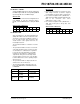
Affected Silicon Revisions
14. Module: Internal Fixed Voltage Reference
(FVR)
The FVRST bit of the CVRCON2 register activates
prematurely (Rev. A4 and A7 only).
Work around
Wait an additional 20 µs after FVRST is sensed
high before using the fixed voltage reference.
Enable the FVR by setting the FVREN bit of the
CVRCON2 register before activating any
peripheral that automatically enables the FVR.
Peripherals that automatically enable the FVR
include the Brown-out Reset, the High/Low
Voltage Detect, and the HFINTOSC.
Affected Silicon Revisions
A4 A7 A9 AB
XXX
X
A4 A7 A9
AB
XXX
X
A4 A7 A9
AB
XXX
X
A4 A7 A9
AB
XXX
X
A4 A7 A9 AB
XXX
X
A4 A7 A9 AB
XXX
X
A4 A7 A9
AB
XX