
Information

© 2005 Microchip Technology Inc. DS80173C-page 3
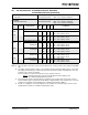
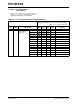
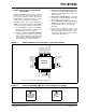
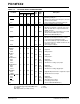
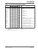
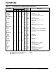
PIC18FXX2
6. Module: Program Memory
A very small number of applications are
experiencing a low failure rate when using self-
write through code types of applications. The most
common of these are bootloader operations. This
failure mechanism is characterized by a few bytes
in program memory not being written as expected.
If this failure is going to occur, it will occur during a
self-write operation. If a failure is not immediately
observed, then there will be no data retention
issues. The failure does not occur when using an
external programmer through In-Circuit Serial
Programming™ (ICSP™).
This failure mechanism is dependent on the
sequence of instructions executed after self-
writes. Good power supply decoupling minimizes
this issue. It is recommended that you use a 0.1 μF
decoupling capacitor with each power pin pair. The
decoupling capacitor should be placed very close
to the power pins.
It is recommended that you perform statistically
significant testing within your application’s
operating range (i.e., temperature and voltage)
with devices from multiple lots.
Work around
1. This work around only applies to PIC18F252
and PIC18F452 devices.
The program memory is divided into discrete
panels and the failure has only been observed
when a table write is executed from the same
panel it is programming. The table write (self-
write) within the same memory panel (0x0000
to 0x3FFF and 0x4000 to 0x7FFF) initiates a
condition that can cause a failure. The
firmware work around is to duplicate the partial
bootloader (two instantiations of write
functions) in two panels and ensure that the
bootloader code always programs a different
panel from where it resides. To accomplish
this, do the following:
• Receive data from communication channel
(normal operation for the bootloader).
• Identify address to be written.
• If writing to an address within the same
memory panel that you are executing from
(0x0000 to 0x3FFF and 0x4000 to 0x7FFF),
then jump to the opposite memory panel. If
the bootloader resides between location
0x0000 to 0x3FFF, and writing to an
address between 0x0000 to 0x3FFF, then
jump to another instantiation of the code
located between 0x4000 to 0x7FFF and
vice versa.
• Always load holding latches (loading of
TABLAT and then TBLWT*) from the oppo-
site panel. This will require duplicate code in
each panel to load data.
• Always initiate write from the opposite
panel. This will require duplicate code in
each panel for the unlock sequence and
setting up the write bit.
• At the end of the successful write, code can
return to the primary panel to get the next
data.
2. Use a similar device from the PIC18F4520
family.