
Information


PIC18FXX2
DS80173C-page 12 © 2005 Microchip Technology Inc.
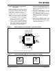
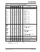
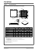
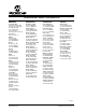
FIGURE 3: 44-PIN QFN PACKAGE
D2
D
A1
A3
A
TOP VIEW
n
1
L
E2
BOTTOM VIEW
B
E
2
PAD
METAL
EXPOSED
p
PIN 1
INDEX ON
EXPOSED PAD
TOP MARKING
INDEX ON
OPTIONAL PIN 1
DETAIL: CONTACT VARIANTS
(PROFILE MAY VARY)
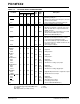
2. REF: Reference Dimension, usually without tolerance, for information purposes only.
1. BSC: Basic Dimension. Theoretically exact value shown without tolerances.
2
A3Base Thickness .010 REF
JEDEC equivalent: M0-220
Exposed Pad Length
Exposed Pad Width
Contact Length
Overall Length
Overall Width
Notes:
Drawing No. C04-103, Revised 05-05-05
*Controlling Parameter
Contact Width
D2
E2
L
E
D
B
See ASME Y14.5M
See ASME Y14.5M
.008
.014
.236
.236
.309
.309
.258
.016
.013
.315
.258
.315
Overall Height
Standoff
Number of Contacts
Pitch
A
p
n
A1
Dimension Limits
Units
.000
.031
MIN
1
.026 BSC
.001
.035
NOM
INCHES
44
2
0.25 REF
8.00
6.55
6.55
0.40
8.00
0.33
.260
.019
.013
.321
.321
.260
0.20
0.35
5.99
5.99
7.85
7.85
0.35
0.48
6.60
6.60
8.15
8.15
0.02
0.90
0.65 BSC
44
MILLIMETERS*
MIN
.039
.002
MAX
0
0.80
NOM
1
0.05
1.00
MAX
Exposed pad varies according to die attach paddle size.
44-Lead Plastic Quad Flat No Lead Package (ML) 8x8 mm Body (QFN)