
Information


© 2008 Microchip Technology Inc. DS80405A-page 3
PIC18F2410/2510/4410/4510
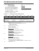
4. Module: 10-Bit Analog-to-Digital
Converter
When the AD clock source is selected as 2 TOSC or
RC (when ADCS<2:0> = 000 or x11), in extremely
rare cases, the EIL (Integral Linearity Error) and
E
DL (Differential Linearity Error) may exceed the
data sheet specification at codes 511 and 512 only.
Work around
Select the AD clock source as 4 TOSC, 8 TOSC,
16 T
OSC, 32 TOSC or 64 TOSC and avoid selecting
2T
OSC or RC.
Date Codes that pertain to this issue:
All engineering and production devices.
5. Module: MSSP
With MSSP in SPI Master mode, FOSC/64 or
Timer2/2 clock rate, and CKE = 0, a write collision
may occur if SSPBUF is loaded immediately after
the transfer is complete. A delay may be required
after the MSSP Interrupt Flag bit, SSPIF, is set or
the Buffer Full bit, BF, is set and before writing
SSPBUF. If the delay is insufficiently short, a write
collision may occur as indicated by the WCOL bit
being set.
Work around
Add a software delay of one SCK period after
detecting the completed transfer and prior to
updating the SSPBUF contents. Verify the WCOL
bit is clear after writing SSPBUF. If the WCOL is
set, clear the bit in software and rewrite the
SSPBUF register.
Date Codes that pertain to this issue:
All engineering and production devices.
6. Module: Enhanced Capture/Compare/
PWM (ECCP)
With the ECCP configured for Half-Bridge PWM
mode (CCP1M<3:0> = 1110), the output may be
corrupted for particular duty cycle selections.
Affected duty cycle values are 0 though 3, and
every subsequent increment of 4 (i.e., 7, 11, 15,
19, etc.).
Work around
None.
Date Codes that pertain to this issue:
All engineering and production devices.
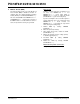
bit 1 WUE: Wake-up Enable bit
Asynchronous mode:
1 = EUSART will continue to sample the RX pin with the interrupt generated on the falling edge; bit
cleared in hardware on following rising edge
0 = RX pin is not monitored or rising edge detected
Synchronous mode:
Unused in this mode.
bit 0 ABDEN: Auto-Baud Detect Enable bit
Asynchronous mode:
1 = Enable baud rate measurement on the next character. Requires reception of a Sync field (55h);
cleared in hardware upon completion.
0 = Baud rate measurement disabled or completed
Synchronous mode:
Unused in this mode.
REGISTER 17-3: BAUDCON: BAUD RATE CONTROL REGISTER (CONTINUED)