
Information


PIC18F2410/2510/4410/4510
DS80293C-page 2 © 2007 Microchip Technology Inc.
2. Module: MSSP
With MSSP in SPI Master mode, FOSC/64 or
Timer2/2 clock rate, and CKE = 0, a write collision
may occur if SSPBUF is loaded immediately after
the transfer is complete. A delay may be required
after the MSSP Interrupt Flag bit, SSPIF, is set or
the Buffer Full bit, BF, is set and before writing
SSPBUF. If the delay is insufficiently short, a write
collision may occur, as indicated by the WCOL bit
being set.
Work around
Add a software delay of one SCK period after
detecting the completed transfer and prior to
updating the SSPBUF contents. Verify the WCOL
bit is clear after writing SSPBUF. If the WCOL is
set, clear the bit in software and rewrite the
SSPBUF register.
Date Codes that pertain to this issue:
All engineering and production devices.
3. Module: Enhanced Capture/Compare/
PWM (ECCP)
With the ECCP configured for Half-Bridge PWM
mode (CCP1M<3:0> = 1110), the output may be
corrupted for particular duty cycle selections.
Affected duty cycle values are 0 though 3, and
every subsequent increment of 4 (i.e., 7, 11, 15,
19, etc.).
Work around
None.
Date Codes that pertain to this issue:
All engineering and production devices.
4. Module: Timer1 and Timer3
When either Timer1 or Timer3 is configured to use the
external clock source in 8-Bit Asynchronous mode
(T1CON<7:0> or T3CON<7:0> = 0xxx x111),
writes to the corresponding TMRxH:TMRxL registers
may not occur as expected.
For the purposes of this issue, instructions that
directly affect the contents of the Timer registers
are considered to be writes. This includes CLRF,
SETF and MOVF instructions.
Work around
Insert a delay of one instruction cycle between
writes to TMRxH and TMRxL. This delay can be a
NOP, or any instruction that does not access the
Timer registers (Example 1).
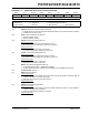
EXAMPLE 1:
Date Codes that pertain to this issue:
All engineering and production devices.
5. Module: Enhanced Universal
Synchronous Receiver
Transmitter (EUSART)
One bit has been added to the BAUDCON register
and one bit has been renamed. The added bit is
RXDTP and is in the location, BAUDCON<5>. The
renamed bit is the TXCKP bit (BAUDCON<4>),
which had been named SCKP.
The TXCKP (BAUDCON<4>) and RXDTP
(BAUDCON<5>) bits enable the TX and RX
signals to be inverted (polarity reversed).
Register 17-3, on page 194, will be changed as
shown on page 3.
Work around
None required.
Date Codes that pertain to this issue:
All engineering and production devices.
CLRF TMR1H
MOVLW T1Offset ; 1 Tcy delay
MOVWF TMR1L