
Datasheet


2010 Microchip Technology Inc. DS41303G-page 321
PIC18F2XK20/4XK20
24.1.1 STANDARD INSTRUCTION SET
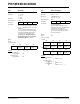
ADDLW ADD literal to W
Syntax: ADDLW k
Operands: 0 k 255
Operation: (W) + k W
Status Affected: N, OV, C, DC, Z
Encoding: 0000 1111 kkkk kkkk
Description: The contents of W are added to the
8-bit literal ‘k’ and the result is placed in
W.
Words: 1
Cycles: 1
Q Cycle Activity:
Q1 Q2 Q3 Q4
Decode Read
literal ‘k’
Process
Data
Write to W
Example
: ADDLW 15h
Before Instruction
W = 10h
After Instruction
W = 25h
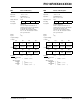
ADDWF ADD W to f
Syntax: ADDWF f {,d {,a}}
Operands: 0 f 255
d [0,1]
a [0,1]
Operation: (W) + (f) dest
Status Affected: N, OV, C, DC, Z
Encoding: 0010 01da ffff ffff
Description: Add W to register ‘f’. If ‘d’ is ‘0’, the
result is stored in W. If ‘d’ is ‘1’, the
result is stored back in register ‘f’
(default).
If ‘a’ is ‘0’, the Access Bank is selected.
If ‘a’ is ‘1’, the BSR is used to select the
GPR bank.
If ‘a’ is ‘0’ and the extended instruction
set is enabled, this instruction operates
in Indexed Literal Offset Addressing
mode whenever f 95 (5Fh). See
Section 24.2.3 “Byte-Oriented and
Bit-Oriented Instructions in Indexed
Literal Offset Mode” for details.
Words: 1
Cycles: 1
Q Cycle Activity:
Q1 Q2 Q3 Q4
Decode Read
register ‘f’
Process
Data
Write to
destination
Example
: ADDWF REG, 0, 0
Before Instruction
W = 17h
REG = 0C2h
After Instruction
W = 0D9h
REG = 0C2h
Note: All PIC18 instructions may take an optional label argument preceding the instruction mnemonic for use in
symbolic addressing. If a label is used, the instruction format then becomes: {label} instruction argument(s).