
Datasheet


2010 Microchip Technology Inc. DS41303G-page 179
PIC18F2XK20/4XK20
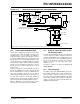
16.4.2 FULL-BRIDGE MODE
In Full-Bridge mode, all four pins are used as outputs.
An example of Full-Bridge application is shown in
Figure 16-6.
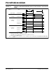
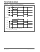
In the Forward mode, pin CCP1/P1A is driven to its
active state, pin P1D is modulated, while P1B and P1C
will be driven to their inactive state as shown in
Figure 16-7.
In the Reverse mode, P1C is driven to its active state,
pin P1B is modulated, while P1A and P1D will be driven
to their inactive state as shown Figure 16-7.
P1A, P1B, P1C and P1D outputs are multiplexed with
the PORT data latches. The associated TRIS bits must
be cleared to configure the P1A, P1B, P1C and P1D
pins as outputs.
FIGURE 16-6: EXAMPLE OF FULL-BRIDGE APPLICATION
P1A
P1C
FET
Driver
FET
Driver
V+
V-
Load
FET
Driver
FET
Driver
P1B
P1D
QA
QB
QD
QC