
Datasheet

PIC18F2XK20/4XK20
DS41303G-page 308 2010 Microchip Technology Inc.
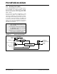
23.2 Watchdog Timer (WDT)
For PIC18F2XK20/4XK20 devices, the WDT is driven
by the LFINTOSC source. When the WDT is enabled,
the clock source is also enabled. The nominal WDT
period is 4 ms and has the same stability as the LFIN-
TOSC oscillator.
The 4 ms period of the WDT is multiplied by a 16-bit
postscaler. Any output of the WDT postscaler is
selected by a multiplexer, controlled by bits in Configu-
ration Register 2H. Available periods range from 4 ms
to 131.072 seconds (2.18 minutes). The WDT and
postscaler are cleared when any of the following events
occur: a SLEEP or CLRWDT instruction is executed, the
IRCF bits of the OSCCON register are changed or a
clock failure has occurred.
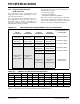
FIGURE 23-1: WDT BLOCK DIAGRAM
Note 1: The CLRWDT and SLEEP instructions
clear the WDT and postscaler counts
when executed.
2: Changing the setting of the IRCF bits of
the OSCCON register clears the WDT
and postscaler counts.
3: When a CLRWDT instruction is executed,
the postscaler count will be cleared.
LFINTOSC Source
WDT
Wake-up
Reset
WDT Counter
Programmable Postscaler
1:1 to 1:32,768
Enable WDT
WDTPS<3:0>
SWDTEN
WDTEN
CLRWDT
4
from Power
Reset
All Device Resets
Sleep
128
Change on IRCF bits
Managed Modes