
Datasheet


PIC18F2XK20/4XK20
DS41303G-page 118 2010 Microchip Technology Inc.
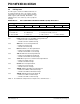
9.8 RCON Register
The RCON register contains flag bits which are used to
determine the cause of the last Reset or wake-up from
Idle or Sleep modes. RCON also contains the IPEN bit
which enables interrupt priorities.
The operation of the SBOREN bit and the Reset flag
bits is discussed in more detail in Section 4.1 “RCON
Register”.
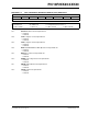
REGISTER 9-10: RCON: RESET CONTROL REGISTER
R/W-0 R/W-1 U-0 R/W-1 R-1 R-1 R/W-0 R/W-0
IPEN SBOREN
(1)
—RITO PD POR
(1)
BOR
bit 7 bit 0
Legend:
R = Readable bit W = Writable bit U = Unimplemented bit, read as ‘0’
-n = Value at POR ‘1’ = Bit is set ‘0’ = Bit is cleared x = Bit is unknown
bit 7 IPEN: Interrupt Priority Enable bit
1 = Enable priority levels on interrupts
0 = Disable priority levels on interrupts (Mid-Range Compatibility mode)
bit 6 SBOREN: Software BOR Enable bit
(1)
For details of bit operation, see Register 4-1.
bit 5 Unimplemented: Read as ‘0’
bit 4 RI: RESET Instruction Flag bit
For details of bit operation, see Register 4-1.
bit 3 TO: Watchdog Time-out Flag bit
For details of bit operation, see Register 4-1.
bit 2 PD: Power-down Detection Flag bit
For details of bit operation, see Register 4-1
bit 1 POR: Power-on Reset Status bit
For details of bit operation, see Register 4-1.
bit 0 BOR: Brown-out Reset Status bit
For details of bit operation, see Register 4-1.
Note 1: Actual Reset values are determined by device configuration and the nature of the device Reset.
See Register 4-1 for additional information.