
Information

© 2005 Microchip Technology Inc. DS80192C-page 1
PIC18F2331/2431/4331/4431
The PIC18F2331/2431/4331/4431 parts you have
received conform functionally to the Device Data Sheet
(DS39616), except for the anomalies described below.
Any Data Sheet Clarification issues related to the
PIC18F2331/2431/4331/4431 will be reported in a
separate Data Sheet errata. Please check the
Microchip web site for any existing issues.
All the issues listed here will be addressed in future
revisions of the PIC18F2331/2431/4331/4431 silicon.
The following silicon errata apply only to
PIC18F2331/2431/4331/4431 devices with these
Device/Revision IDs:
1. Module: PCPWM
When the PCPWM is operated in Complementary
mode with a non-zero dead-time value and the
duty cycle results in an active-low time of less than
1T
CY, the PWM generator will miss the rising edge
for a new PWM period and the PWM output will
alternate between one PWM period high and one
PWM period low.
Work around
When in Complementary mode with a non-zero
dead-time value, ensure that the active-low time
will always be greater than 1 TCY. In other words,
when dead time is not equal to zero, ensure that:
PDCH:PDCL < (4 * PTPERH:PTPERL)
or
PDCH:PDCL > (4 * (PTPERH:PTPERL + 1))
Date Codes that pertain to this issue:
All engineering and production devices.
2. Module: PCPWM
When the PCPWM is operated in Center-Aligned
mode with double updates and the duty cycle
alternates on each update between a zero and
non-zero value, an incorrect waveform is gener-
ated (the PWM output will alternate between one
PWM period high and one PWM period low). If in
Complementary mode, dead time will not be
inserted properly.
Work around
Do not use zero duty cycle when in Center-Aligned
mode with double updates. Instead of zero, set the
duty cycle to a small, non-zero value.
Date Codes that pertain to this issue:
All engineering and production devices.
3. Module: PCPWM
When the PCPWM is operated in Center-Aligned
mode with double updates and the duty cycle
alternates on each update between a greater than
100% duty cycle and a non-zero value, an incorrect
waveform is generated.
Work around
Do not use equal to or greater than 100% duty cycle
when in Center-Aligned mode with double updates.
Ensure that the maximum duty cycle value is
always smaller than or equal to the PWM period,
i.e., PDCH:PDCL ≤ (4 * (PTPERH:PTPERL)).
Date Codes that pertain to this issue:
All engineering and production devices.
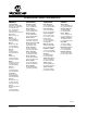
Part Number Device ID Revision ID
PIC18F2331 00 1000 111 00010
PIC18F2431 00 1000 110 00010
PIC18F4331 00 1000 101 00010
PIC18F4431 00 1000 100 00010
The Device IDs (DEVID1 and DEVID2) are located at
addresses 3FFFFEh:3FFFFFh in the device’s
configuration space. They are shown in hexadecimal
in the format “DEVID2 DEVID1”.
PIC18F2331/2431/4331/4431 Rev. A3 Silicon Errata