
Information

2010 Microchip Technology Inc. DS80285C-page 5
PIC18F2221/2321/4221/4321
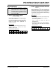
2. Module: CONFIG4L Register
Register 23-5 CONFIG4L: Configuration Regis-
ter 4 Low (Byte Address 300006h), on Page 258,
has been changed to designate Bit 3 of
CONFIG4L as unimplemented.
The register is changed as shown.
REGISTER 23-5: CONFIG4L: CONFIGURATION REGISTER 4 LOW (BYTE ADDRESS 300006h)
R/P-1 R/P-0 U-0 U-0 U-0 R/P-1 U-0 R/P-1
DEBUG
XINST BBSIZ1 BBSIZ0 —LVP —STVREN
bit 7 bit 0
Legend:
R = Readable bit W = Writable bit U = Unimplemented bit, read as ‘0’
-n = Value at POR ‘1’ = Bit is set ‘0’ = Bit is cleared x = Bit is unknown
bit 7 DEBUG
: Background Debugger Enable bit
1 = Background debugger disabled, RB6 and RB7 configured as general purpose I/O pins
0 = Background debugger enabled, RB6 and RB7 are dedicated to In-Circuit Debug
bit 6 XINST: Extended Instruction Set Enable bit
1 = Instruction set extension and Indexed Addressing mode enabled
0 = Instruction set extension and Indexed Addressing mode disabled (Legacy mode)
bit 5-4 BBSIZ<1:0>: Boot Block Size Select bits
Feature2 Devices:
1x = 1024 Words
01 = 512 Words
00 = 256 Words
Feature1 Devices:
1x = 512 Words
x1 = 512 Words
00 = 256 Words
bit 3 Unimplemented: Read as ‘0’
bit 2 LVP: Single-Supply ICSP™ Enable bit
1 = Single-Supply ICSP enabled
0 = Single-Supply ICSP disabled
bit 1 Unimplemented: Read as ‘0’
bit 0 STVREN: Stack Full/Underflow Reset Enable bit
1 = Stack full/underflow will cause Reset
0 = Stack full/underflow will not cause Reset