
Information


© 2008 Microchip Technology Inc. DS80334B-page 3
PIC18F2220/2320/4220/4320
3. Module: OSCTUN2 REGISTER
The bullet points in the second paragraph of
Section 2.6.3 “OSCTUN2 Register” on page 24
are modified. The modified values indicate that the
OSCTUNE register does not affect the INTRC
frequency. The modified values are indicated in
bold text in the following excerpt of the section:
• If TUNSEL (OSCTUN2<7>) is clear – The
INTOSC clock frequency can be adjusted by
the TUN5:TUN1 bits in OSCTUNE<5:1> without
affecting the INTRC frequency
(see Register 2-1:OSCTUNE).
• If TUNSEL (OSCTUN2<7>) is set – The INTRC
clock frequency can be adjusted by the
TUN5:TUN1 bits in OSCTUN2<5:1> without
affecting the INTOSC frequency
(see Register 2-2: OSCTUN2).
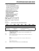
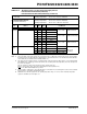
REGISTER 2-2: OSCTUN2: INTRC OSCILLATOR
TUNING REGISTER values are modified. The
modified content for bit 7 is indicated in bold text and
the second sentence in bit 0 is deleted, and the
modified content is indicated in bold text in
Register 2-2.
REGISTER 2-2: OSCTUN2: INTRC OSCILLATOR TUNING REGISTER
R/W-0 U-0 R/W-0 R/W-0 R/W-0 R/W-0 R/W-0 R/W-0
TUNSEL
— TUN5 TUN4 TUN3 TUN2 TUN1 TUN0
bit 7 bit 0
Legend:
R = Readable bit W = Writable bit U = Unimplemented bit, read as ‘0’
-n = Value at POR ‘1’ = Bit is set ‘0’ = Bit is cleared x = Bit is unknown
bit 7 TUNSEL: INTRC Frequency bit
1 = INTRC frequency adjusted according to the values of the OSCTUN2<5:1> bits
0 = INTRC not affected
bit 6 Unimplemented: Read as ‘0’
bit 5-1 TUN<5:1>: Frequency Tuning bits – Adjusts the frequency of INTRC when TUNSEL is set
011111 = Maximum frequency
•
•
000001
000000 = Center frequency. Oscillator module is running at the calibrated frequency
111111
•
•
100000 = Minimum frequency
bit 0 TUN<0>: Placeholder. This bit has no effect on the INTRC frequency.