
Datasheet


PIC18F1230/1330
DS39758D-page 150 2009 Microchip Technology Inc.
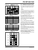
REGISTER 15-3: BAUDCON: BAUD RATE CONTROL REGISTER
R/W-0 R-1 R/W-0 R/W-0 R/W-0 U-0 R/W-0 R/W-0
ABDOVF RCIDL RXDTP TXCKP BRG16
— WUE ABDEN
bit 7 bit 0
Legend:
R = Readable bit W = Writable bit U = Unimplemented bit, read as ‘0’
-n = Value at POR ‘1’ = Bit is set ‘0’ = Bit is cleared x = Bit is unknown
bit 7 ABDOVF: Auto-Baud Acquisition Rollover Status bit
1 = A BRG rollover has occurred during Auto-Baud Rate Detect mode (must be cleared in software)
0 = No BRG rollover has occurred
bit 6 RCIDL: Receive Operation Idle Status bit
1 = Receive operation is Idle
0 = Receive operation is active
bit 5 RXDTP: Received Data Polarity Select bit
Asynchronous mode
:
1 = RX data is inverted
0 = RX data is not inverted
S
ynchronous mode:
Unused in this mode.
bit 4 TXCKP: Clock and Data Polarity Select bit
Asynchronous mode:
1 = Idle state for transmit (TX) is a low level
0 = Idle state for transmit (TX) is a high level
S
ynchronous mode:
1 = Idle state for clock (CK) is a high level
0 = Idle state for clock (CK) is a low level
bit 3 BRG16: 16-Bit Baud Rate Register Enable bit
1 = 16-bit Baud Rate Generator – SPBRGH and SPBRG
0 = 8-bit Baud Rate Generator – SPBRG only (Compatible mode), SPBRGH value ignored
bit 2 Unimplemented: Read as ‘0’
bit 1 WUE: Wake-up Enable bit
Asynchronous mode:
1 = EUSART will continue to sample the RX pin – interrupt generated on falling edge; bit cleared in
hardware on following rising edge
0 = RX pin not monitored or rising edge detected
Synchronous mode:
Unused in this mode.
bit 0 ABDEN: Auto-Baud Detect Enable bit
Asynchronous mode:
1 = Enable baud rate measurement on the next character. Requires reception of a Sync field (55h);
cleared in hardware upon completion
0 = Baud rate measurement disabled or completed
Synchronous mode:
Unused in this mode.