
Datasheet


PIC18F1230/1330
DS39758D-page 142 2009 Microchip Technology Inc.
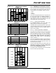
FIGURE 14-23: PWM I/O PIN BLOCK DIAGRAM
14.11.3 PWM OUTPUT PIN RESET STATES
The PWMPIN Configuration bit determines the PWM
output pins to be PWM output pins, or digital I/O pins,
after the device comes out of Reset. If the PWMPIN
Configuration bit is unprogrammed (default), the
PWMEN2:PWMEN0 control bits will be cleared on a
device Reset. Consequently, all PWM outputs will be
tri-stated and controlled by the corresponding PORT
and TRIS registers. If the PWMPIN Configuration bit is
programmed low, the PWMEN2:PWMEN0 control bits
will be set to ‘100’ on a device Reset:
All PWM pins will be enabled for PWM output and will
have the output polarity defined by the HPOL and
LPOL Configuration bits.
14.12 PWM Fault Input
There is one Fault input associated with the PWM
module. The main purpose of the input Fault pin is to
disable the PWM output signals and drive them into an
inactive state. The action of the Fault input is performed
directly in hardware so that when a Fault occurs, it can
be managed quickly and the PWMs outputs are put into
an inactive state to save the power devices connected
to the PWMs.
The PWM Fault input is FLTA
, which can come from
I/O pins, the CPU or another module. The FLTA
pin is
an active-low input so it is easy to “OR” many sources
to the same input.
The FLTCONFIG register (Register 14-8) defines the
settings of the FLTA
input.
14.12.1 FAULT PIN ENABLE BIT
By setting the bit FLTAEN in the FLTCONFIG register,
the corresponding Fault input is enabled. If FLTAEN bit
is cleared, then the Fault input has no effect on the
PWM module.
Data Bus
WR PORT
WR TRIS
RD PORT
Data Latch
TRIS Latch
P
V
SS
I/O pin
Q
D
Q
CK
Q
D
Q
CK
Q
D
EN
N
VDD
RD TRIS
Schmitt
Trigger
TTL or
0
1
PWM Pin Enable
PWM Signal from Module
Note: I/O pin has protection diodes to VDD and VSS. PWM polarity selection logic not shown for clarity.
Note: The inactive state of the PWM pins is
dependent on the HPOL and LPOL Con-
figuration bit settings, which define the
active and inactive state for PWM outputs.