
Datasheet


PIC18F1230/1330
2009 Microchip Technology Inc. DS39758D-page 137
The actual dead time is calculated from the DTCON
register as follows:
Dead Time = Dead-Time Value/(F
OSC/Prescaler)
Table 14-3 shows example dead-time ranges as a
function of the input clock prescaler selected and the
device operating frequency.
TABLE 14-3: EXAMPLE DEAD-TIME
RANGES
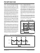
14.7.4 DEAD-TIME DISTORTION
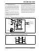
14.8 Independent PWM Output
Independent PWM mode is used for driving the loads
(as shown in Figure 14-19) that drive one winding of a
switched reluctance motor. A particular PWM output
pair is configured in the Independent Output mode
when the corresponding PMODx bit in the PWMCON0
register is set. No dead-time control is implemented
between the PWM I/O pins when the module is operat-
ing in the Independent PWM mode and both I/O pins
are allowed to be active simultaneously. This mode can
also be used to drive stepper motors.
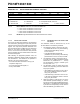
14.8.1 DUTY CYCLE ASSIGNMENT IN THE
INDEPENDENT PWM MODE
In the Independent PWM mode, each duty cycle gener-
ator is connected to both PWM output pins in a given
PWM output pair. The odd and the even PWM output
pins are driven with a single PWM duty cycle generator.
PWM1 and PWM0 are driven by the PWM channel
which uses the PDC0 register to set the duty cycle,
PWM3 and PWM2 with PDC1, and PWM5 and PWM4
with PDC2 (see Figure 14-3 and Register 14-3).
F
OSC
(MHz)
MIPS
Prescaler
Selection
Dead-Time
Min
Dead-Time
Max
40 10 F
OSC/2 50 ns 3.2 s
40 10 F
OSC/4 100 ns 6.4 s
40 10 FOSC/8 200 ns 12.8 s
40 10 FOSC/16 400 ns 25.6 s
32 8 F
OSC/2 62.5 ns 4 s
32 8 F
OSC/4 125 ns 8 s
32 8 FOSC/8 250 ns 16 s
32 8 F
OSC/16 500 ns 32 s
25 6.25 FOSC/2 80 ns 5.12 s
25 6.25 FOSC/4 160 ns 10.2 s
25 6.25 F
OSC/8 320 ns 20.5 s
25 6.25 FOSC/16 640 ns 41 s
20 5 FOSC/2 100 ns 6.4 s
20 5 F
OSC/4 200 ns 12.8 s
20 5 FOSC/8 400 ns 25.6 s
20 5 FOSC/16 800 ns 51.2 s
10 2.5 F
OSC/2 200 ns 12.8 s
10 2.5 FOSC/4 400 ns 25.6 s
10 2.5 FOSC/8 800 ns 51.2 s
10 2.5 F
OSC/16 1.6 s 102.4 s
51.25FOSC/2 400 ns 25.6 s
51.25FOSC/4 800 ns 51.2 s
51.25F
OSC/8 1.6 s 102.4 s
51.25FOSC/16 3.2 s 204.8 s
41F
OSC/2 0.5 s32 s
41F
OSC/4 1 s64 s
41FOSC/8 2 s128 s
41F
OSC/16 4 s256 s
Note 1: For small PWM duty cycles, the ratio of
dead time to the active PWM time may
become large. In this case, the inserted
dead time will introduce distortion into
waveforms produced by the PWM mod-
ule. The user can ensure that dead-time
distortion is minimized by keeping the
PWM duty cycle at least three times
larger than the dead time. A similar effect
occurs for duty cycles at or near 100%.
The maximum duty cycle used in the
application should be chosen such that
the minimum inactive time of the signal is
at least three times larger than the dead
time. If the dead time is greater or equal
to the duty cycle of one of the PWM
output pairs, then that PWM pair will be
inactive for the whole period.
2: Changing the dead-time values in
DTCON when the PWM is enabled may
result in an undesirable situation. Disable
the PWM (PTEN = 0) before changing the
dead-time value.