
Datasheet


PIC18F1230/1330
2009 Microchip Technology Inc. DS39758D-page 123
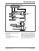
REGISTER 14-3: PWMCON0: PWM CONTROL REGISTER 0
U-0 R/W-1
(1)
R/W-1
(1)
R/W-1
(1)
U-0 R/W-0 R/W-0 R/W-0
— PWMEN2 PWMEN1 PWMEN0 — PMOD2 PMOD1 PMOD0
bit 7 bit 0
Legend:
R = Readable bit W = Writable bit U = Unimplemented bit, read as ‘0’
-n = Value at POR ‘1’ = Bit is set ‘0’ = Bit is cleared x = Bit is unknown
bit 7 Unimplemented: Read as ‘0’
bit 6-4 PWMEN2:PWMEN0: PWM Module Enable bits
(1)
111 = All odd PWM I/O pins enabled for PWM output
110 = PWM1, PWM3 pins enabled for PWM output
10x = All PWM I/O pins enabled for PWM output
011 = PWM0, PWM1, PWM2 and PWM3 I/O pins enabled for PWM output
010 = PWM0 and PWM1 pins enabled for PWM output
001 = PWM1 pin is enabled for PWM output
000 = PWM module disabled; all PWM I/O pins are general purpose I/O
bit 3 Unimplemented: Read as ‘0’
bit 2-0 PMOD2:PMOD0: PWM Output Pair Mode bits
For PMOD0
:
1 = PWM I/O pin pair (PWM0, PWM1) is in the Independent mode
0 = PWM I/O pin pair (PWM0, PWM1) is in the Complementary mode
For PMOD1:
1 = PWM I/O pin pair (PWM2, PWM3) is in the Independent mode
0 = PWM I/O pin pair (PWM2, PWM3) is in the Complementary mode
For PMOD2:
1 = PWM I/O pin pair (PWM4, PWM5) is in the Independent mode
0 = PWM I/O pin pair (PWM4, PWM5) is in the Complementary mode
Note 1: Reset condition of PWMEN bits depends on the PWMPIN Configuration bit of CONFIG3L.