
Datasheet


PIC18F1230/1330
2009 Microchip Technology Inc. DS39758D-page 121
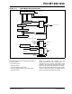
FIGURE 14-4: PWM TIME BASE BLOCK DIAGRAM
The PWM time base can be configured for four different
modes of operation:
• Free-Running mode
• Single-Shot mode
• Continuous Up/Down Count mode
• Continuous Up/Down Count mode with interrupts
for double updates
These four modes are selected by the
PTMOD1:PTMOD0 bits in the PTCON0 register. The
Free-Running mode produces edge-aligned PWM
generation. The Continuous Up/Down Count modes
produce center-aligned PWM generation. The Single-
Shot mode allows the PWM module to support pulse
control of certain Electronically Commutated Motors
(ECMs) and produces edge-aligned operation.
PTMR Register
PTPER
Comparator
PTPER Buffer
Comparator
Zero Match
Period Match
PTMOD1
Up/Down
Timer Reset
FOSC/4
Prescaler
1:1, 1:4, 1:16, 1:64
Timer
Direction
Control
Clock
Control
Period Load
Duty Cycle Load
PTMOD1
Period Match
Zero Match
PTMR Clock
Interrupt
Control
PTMOD1
Period Match
Zero Match
PTMOD0
PTMOD0
PTEN
PTIF
PTDIR
PTMR Clock
Update Disable (UDIS)
Postscaler
1:1-1:16