
Datasheet


PIC18F1230/1330
2009 Microchip Technology Inc. DS39758D-page 21
3.0 OSCILLATOR
CONFIGURATIONS
3.1 Oscillator Types
PIC18F1230/1330 devices can be operated in ten
different oscillator modes. The user can program the
Configuration bits, FOSC3:FOSC0, in Configuration
Register 1H to select one of these ten modes:
1. LP Low-Power Crystal
2. XT Crystal/Resonator
3. HS High-Speed Crystal/Resonator
4. HSPLL High-Speed Crystal/Resonator
with PLL enabled
5. RC External Resistor/Capacitor with
F
OSC/4 output on RA6
6. RCIO External Resistor/Capacitor with I/O
on RA6
7. INTIO1 Internal Oscillator with F
OSC/4 output
on RA6 and I/O on RA7
8. INTIO2 Internal Oscillator with I/O on RA6
and RA7
9. EC External Clock with F
OSC/4 output
10. ECIO External Clock with I/O on RA6
3.2 Crystal Oscillator/Ceramic
Resonators
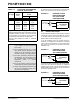
In XT, LP, HS or HSPLL Oscillator modes, a crystal or
ceramic resonator is connected to the OSC1 and
OSC2 pins to establish oscillation. Figure 3-1 shows
the pin connections.
The oscillator design requires the use of a parallel
resonant crystal.
FIGURE 3-1: CRYSTAL/CERAMIC
RESONATOR OPERATION
(XT, LP, HS OR HSPLL
CONFIGURATION)
TABLE 3-1: CAPACITOR SELECTION FOR
CERAMIC RESONATORS
Note: Use of a series resonant crystal may give
a frequency out of the crystal
manufacturer’s specifications.
Typical Capacitor Values Used:
Mode Freq OSC1 OSC2
XT 3.58 MHz
4.19 MHz
4 MHz
4 MHz
15 pF
15 pF
30 pF
50 pF
15 pF
15 pF
30 pF
50 pF
Capacitor values are for design guidance only.
Different capacitor values may be required to produce
acceptable oscillator operation. The user should test
the performance of the oscillator over the expected
V
DD and temperature range for the application.
See the notes following Table 3-2 for additional
information.
Note 1: See Table 3-1 and Table 3-2 for initial values of
C1 and C2.
2: A series resistor (R
S) may be required for AT
strip cut crystals.
3: R
F varies with the oscillator mode chosen.
C1
(1)
C2
(1)
XTAL
OSC2
OSC1
RF
(3)
Sleep
To
Logic
PIC18FXXXX
RS
(2)
Internal