
Datasheet


PIC18F1230/1330
DS39758D-page 202 2009 Microchip Technology Inc.
20.2 Watchdog Timer (WDT)
For PIC18F1230/1330 devices, the WDT is driven by
the INTRC source. When the WDT is enabled, the
clock source is also enabled. The nominal WDT period
is 4 ms and has the same stability as the INTRC
oscillator.
The 4 ms period of the WDT is multiplied by a 16-bit
postscaler. Any output of the WDT postscaler is
selected by a multiplexer, controlled by bits in Configu-
ration Register 2H. Available periods range from 4 ms
to 131.072 seconds (2.18 minutes). The WDT and
postscaler are cleared when any of the following events
occur: a SLEEP or CLRWDT instruction is executed, the
IRCF bits (OSCCON<6:4>) are changed or a clock
failure has occurred.
20.2.1 CONTROL REGISTER
Register 20-15 shows the WDTCON register. This is a
readable and writable register which contains a control
bit that allows software to override the WDT enable
Configuration bit, but only if the Configuration bit has
disabled the WDT.
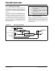
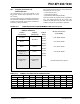
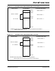
FIGURE 20-1: WDT BLOCK DIAGRAM
Note 1: The CLRWDT and SLEEP instructions
clear the WDT and postscaler counts
when executed.
2: Changing the setting of the IRCF bits
(OSCCON<6:4>) clears the WDT and
postscaler counts.
3: When a CLRWDT instruction is executed,
the postscaler count will be cleared.
INTRC Source
WDT
Wake-up from
Reset
WDT Counter
Programmable Postscaler
1:1 to 1:32,768
Enable WDT
WDTPS<3:0>
SWDTEN
WDTEN
CLRWDT
4
Power-Managed
Reset
All Device Resets
Sleep
128
Change on IRCF bits
Modes