
Datasheet


2009 Microchip Technology Inc. DS39758D-page 17
PIC18F1230/1330
2.0 GUIDELINES FOR GETTING
STARTED WITH PIC18F
MICROCONTROLLERS
2.1 Basic Connection Requirements
Getting started with the PIC18F1230/1330 family of
8-bit microcontrollers requires attention to a minimal
set of device pin connections before proceeding with
development.
The following pins must always be connected:
•All V
DD and VSS pins
(see Section 2.2 “Power Supply Pins”)
•All AV
DD and AVSS pins, regardless of whether or
not the analog device features are used
(see Section 2.2 “Power Supply Pins”)
•M
CLR pin
(see Section 2.3 “Master Clear (MCLR) Pin”)
These pins must also be connected if they are being
used in the end application:
• PGC/PGD pins used for In-Circuit Serial
Programming™ (ICSP™) and debugging purposes
(see Section 2.4 “ICSP Pins”)
• OSCI and OSCO pins when an external oscillator
source is used
(see Section 2.5 “External Oscillator Pins”)
Additionally, the following pins may be required:
•V
REF+/VREF- pins are used when external voltage
reference for analog modules is implemented
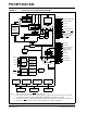
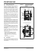
The minimum mandatory connections are shown in
Figure 2-1.
FIGURE 2-1: RECOMMENDED
MINIMUM CONNECTIONS
Note: The AVDD and AVSS pins must always be
connected, regardless of whether any of
the analog modules are being used.
PIC18FXXXX
VDD
VSS
VDD
VSS
VSS
VDD
AVDD
AVSS
VDD
VSS
C1
R1
V
DD
MCLR
R2
C2
(1)
C3
(1)
C4
(1)
C5
(1)
C6
(1)
Key (all values are recommendations):
C1 through C6: 0.1 µF, 20V ceramic
R1: 10 kΩ
R2: 100Ω to 470Ω
Note 1: The example shown is for a PIC18F device
with five V
DD/VSS and AVDD/AVSS pairs.
Other devices may have more or less pairs;
adjust the number of decoupling capacitors
appropriately.