
Datasheet


PIC18F1230/1330
DS39758D-page 14 2009 Microchip Technology Inc.
PORTA is a bidirectional I/O port.
RA0/AN0/INT0/KBI0/
CMP0
RA0
AN0
INT0
KBI0
CMP0
1126
I/O
I
I
I
I
TTL
Analog
ST
TTL
Analog
Digital I/O.
Analog input 0.
External interrupt 0.
Interrupt-on-change pin.
Comparator 0 input.
RA1/AN1/INT1/KBI1
RA1
AN1
INT1
KBI1
2227
I/O
I
I
I
TTL
Analog
ST
TTL
Digital I/O.
Analog input 1.
External interrupt 1.
Interrupt-on-change pin.
RA2/TX/CK
RA2
TX
CK
677
I/O
O
I/O
TTL
—
ST
Digital I/O.
EUSART asynchronous transmit.
EUSART synchronous clock.
RA3/RX/DT
RA3
RX
DT
788
I/O
I
I/O
TTL
ST
ST
Digital I/O.
EUSART asynchronous receive.
EUSART synchronous data.
RA4/T0CKI/AN2/V
REF+
RA4
T0CKI
AN2
V
REF+
3328
I/O
I
I
I
TTL
ST
Analog
Analog
Digital I/O.
Timer0 external clock input.
Analog input 2.
A/D reference voltage (high) input.
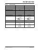
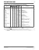
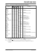
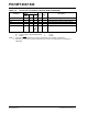
TABLE 1-2: PIC18F1230/1330 PINOUT I/O DESCRIPTIONS (CONTINUED)
Pin Name
Pin Number
Pin
Type
Buffer
Type
Description
PDIP,
SOIC
SSOP QFN
Legend: TTL = TTL compatible input CMOS = CMOS compatible input or output
ST = Schmitt Trigger input with CMOS levels I = Input
O = Output P = Power
Note 1: Placement of FLTA
depends on the value of Configuration bit, FLTAMX, of CONFIG3H.
2: Placement of T1OSI and T1OSO/T1CKI depends on the value of Configuration bit, T1OSCMX, of
CONFIG3H.