
Datasheet


PIC18F1230/1330
DS39758D-page 134 2009 Microchip Technology Inc.
14.6.5 COMPLEMENTARY PWM
OPERATION
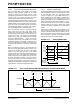
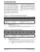
The Complementary mode of PWM operation is useful
to drive one or more power switches in half-bridge
configuration, as shown in Figure 14-16. This inverter
topology is typical for a 3-phase induction motor,
brushless DC motor or 3-phase Uninterruptible Power
Supply (UPS) control applications.
Each upper/lower power switch pair is fed by a
complementary PWM signal. Dead time may be
optionally inserted during device switching, where both
outputs are inactive for a short period (see
Section 14.7 “Dead-Time Generators”).
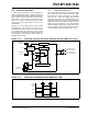
In Complementary mode, the duty cycle comparison
units are assigned to the PWM outputs as follows:
• PDC0 register controls PWM1/PWM0 outputs
• PDC1 register controls PWM3/PWM2 outputs
• PDC2 register controls PWM5/PWM4 outputs
PWM1/3/5 are the main PWMs that are controlled by
the PDCx registers and PWM0/2/4 are the
complemented outputs. When using the PWMs to
control the half-bridge, the odd number PWMs can be
used to control the upper power switch and the even
numbered PWMs can be used for the lower switches.
FIGURE 14-16: TYPICAL LOAD FOR
COMPLEMENTARY PWM
OUTPUTS
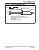
The Complementary mode is selected for each PWM
I/O pin pair by clearing the appropriate PMODx bit in
the PWMCON0 register. The PWM I/O pins are set to
Complementary mode by default upon all kinds of
device Resets.
+V
PWM1
PWM0
PWM3
PWM2
PWM5
PWM4
3-Phase
Load