
Datasheet


PIC18F1230/1330
2009 Microchip Technology Inc. DS39758D-page 133
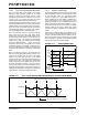
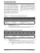
FIGURE 14-14: DUTY CYCLE UPDATE TIMES IN CONTINUOUS UP/DOWN COUNT MODE WITH
DOUBLE UPDATES
14.6.4 CENTER-ALIGNED PWM
Center-aligned PWM signals are produced by the
module when the PWM time base is configured in a
Continuous Up/Down Count mode (see Figure 14-15).
The PWM compare output is driven to the active state
when the value of the Duty Cycle register matches the
value of PTMR and the PWM time base is counting
downwards (PTDIR = 1). The PWM compare output
will be driven to the inactive state when the PWM time
base is counting upwards (PTDIR = 0) and the value in
the PTMR register matches the duty cycle value. If the
value in a particular Duty Cycle register is zero, then
the output on the corresponding PWM pin will be
inactive for the entire PWM period. In addition, the
output on the PWM pin will be active for the entire PWM
period if the value in the Duty Cycle register is equal to
or greater than the value in the PTPER register.
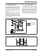
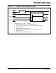
FIGURE 14-15: START OF CENTER-ALIGNED PWM
PTMR Value
PWM Output
Duty Cycle Value Loaded from Buffer Register
New Values Written to Duty Cycle Buffer
Note: When the PWM is started in Center-
Aligned mode, the PWM Time Base
Period register (PTPER) is loaded into the
PWM Time Base register (PTMR) and the
PTMR is configured automatically to start
down counting. This is done to ensure that
all the PWM signals don’t start at the same
time.
0
PTPER
PTMR
Value
Period
Period/2
Duty
Cycle
Start of
First
PWM
Period
Period
Duty Cycle