
Datasheet


PIC18F1230/1330
DS39758D-page 128 2009 Microchip Technology Inc.
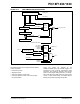
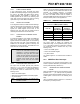
14.4.4 INTERRUPTS IN DOUBLE UPDATE
MODE
This mode is available in Continuous Up/Down Count
mode. In the Double Update mode (PTMOD<1:0> = 11),
an interrupt event is generated each time the PTMR
register is equal to zero and each time the PTMR
matches the PTPER register. Figure 14-8 shows the
interrupts in Continuous Up/Down Count mode with
double updates.
The Double Update mode provides two additional
functions to the user in Center-Aligned mode.
1. The control loop bandwidth is doubled because
the PWM duty cycles can be updated twice per
period.
2. Asymmetrical center-aligned PWM waveforms
can be generated, which are useful for
minimizing output waveform distortion in certain
motor control applications.
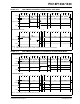
FIGURE 14-8: PWM TIME BASE INTERRUPTS, CONTINUOUS UP/DOWN COUNT MODE WITH
DOUBLE UPDATES
Note: Do not change the PTMOD bits while
PTEN is active. It will yield unexpected
results. To change the PWM Timer mode
of operation, first clear the PTEN bit, load
PTMOD bits with required data and then
set PTEN.
Q2Q1 Q3 Q4Q2Q1 Q3 Q4 Q2Q1 Q3 Q4 Q2Q1 Q3 Q4 Q2Q1 Q3 Q4
1
1
OSC1
PTMR
3FDh
3FEh
3FFh 3FEh 3FDh
1
Case 1: PTMR Counting Upwards
Q2Q1 Q3 Q4Q2Q1 Q3 Q4 Q2Q1 Q3 Q4 Q2Q1 Q3 Q4 Q2Q1 Q3 Q4
1
1
OSC1
PTMR
002h 001h 000h 001h 002h
1
Case 2: PTMR Counting Downwards
2
Note 1: Interrupt flag bit, PTIF, is sampled here (every Q1).
2: PWM Time Base Period register, PTPER, is loaded with the value 3FFh for this example.
1
1
PTIF bit
PTMR_INT_REQ
PTIF bit
PTMR_INT_REQ
A: PRESCALER = 1:1
PTDIR bit
PTDIR bit