
Datasheet


PIC18F1230/1330
2009 Microchip Technology Inc. DS39758D-page 117
14.0 POWER CONTROL PWM
MODULE
The Power Control PWM module simplifies the task of
generating multiple, synchronized Pulse-Width
Modulated (PWM) outputs for use in the control of
motor controllers and power conversion applications.
In particular, the following power and motion control
applications are supported by the PWM module:
• Three-Phase and Single-Phase AC Induction
Motors
• Switched Reluctance Motors
• Brushless DC (BLDC) Motors
• Uninterruptible Power Supplies (UPS)
• Multiple DC Brush Motors
The PWM module has the following features:
• Up to six PWM I/O pins with three duty cycle
generators. Pins can be paired to acquire a
complete half-bridge control.
• Up to 14-bit resolution, depending upon the PWM
period.
• “On-the-fly” PWM frequency changes.
• Edge and Center-Aligned Output modes.
• Single-Pulse Generation mode.
• Programmable dead-time control between paired
PWMs.
• Interrupt support for asymmetrical updates in
Center-Aligned mode.
• Output override for Electrically Commutated Motor
(ECM) operation; for example, BLDC.
• Special Event Trigger comparator for triggering A/D
conversion.
• PWM outputs disable feature sets PWM outputs to
their inactive state when in Debug mode.
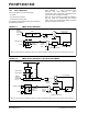
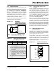
The Power Control PWM module supports three PWM
generators and six output channels on PIC18F1230/
1330 devices. A simplified block diagram of the module
is shown in Figure 14-1. Figure 14-2 and Figure 14-3
show how the module hardware is configured for each
PWM output pair for the Complementary and
Independent Output modes.
Each functional unit of the PWM module will be
discussed in subsequent sections.